Solution Manual For Structural Wood Design: ASD/LRFD, 2nd Edition
Preview Extract
Chapter 2
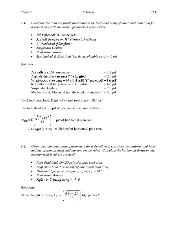
2-1.
Solutions
S2-1
Calculate the total uniformly distributed roof dead load in psf of horizontal plan area for
a sloped roof with the design parameters given below.
โข
โข
โข
โข
โข
โข
2×8 rafters at 24โ on centers
Asphalt shingles on ยฝโ plywood sheathing
6โ insulation (fiberglass)
Suspended Ceiling
Roof slope: 6-in-12
Mechanical & Electrical (i.e. ducts, plumbing etc) = 5 psf
Solution:
2×8 rafters at 24โ on-centers
= 1.2 psf
Asphalt shingles (assume ยผโ shingles)
= 2.0 psf
ยฝโ plywood sheathing = (4 x 0.4 psf/1/8โ plywood) = 1.6 psf
6โ insulation (fiberglass) = 6 x 1.1 psf/in.
= 6.6 psf
Suspended Ceiling
= 2.0 psf
Mechanical & Electrical (i.e. ducts, plumbing etc) = 5.0 psf
Total roof dead load, D (psf of sloped roof area) = 18.4 psf
The total dead load in psf of horizontal plan area will be:
๏ฆ
2
2๏ถ
w DL = D ๏ง๏ง 6 +12 ๏ท๏ท , psf of horizontal plan area
12
๏ง
๏ท
๏จ
๏ธ
=18.4psf (1.118) = 20.6 psf of horizontal plan area
2-2.
Given the following design parameters for a sloped roof, calculate the uniform total load
and the maximum shear and moment on the rafter. Calculate the horizontal thrust on the
exterior wall if rafters are used.
โข
โข
โข
โข
โข
Roof dead load, D= 20 psf (of sloped roof area)
Roof snow load, S = 40 psf (of horizontal plan area)
Horizontal projected length of rafter, L2 =14 ft
Roof slope: 4-in-12
Rafter or Truss spacing = 4โ 0
Solutions:
๏ฆ
2
2๏ถ
Sloped length of rafter, L1 = ๏ง๏ง 4 +12 ๏ท๏ท (14 ft ) =14.8 ft
12
๏ง
๏ท
๏จ
๏ธ
Chapter 2
Solutions
S2-2
Using the load combinations in section 2.1, the total load in psf of horizontal plan area will be:
๏ฆL ๏ถ
wTL = D ๏ง 1 ๏ท + (Lr or S or R), psf of horizontal plan area
๏งL ๏ท
๏จ 2๏ธ
๏ฆ
๏ถ
= 20 psf ๏ง๏ง 14.8′ ๏ท๏ท + 40 psf
๏จ 14′ ๏ธ
= 61.1 psf of horizontal plan area
The total load in pounds per horizontal linear foot (Ib/ft) is given as,
wTL (Ib/ft) = wTL (psf) x Tributary width (TW) or Spacing of rafters
= 61.1 psf (4 ft) = 244.4 lb/ft.
h = (4/12) (14 ft) = 4.67 ft
The horizontal thrust H is,
H=
๏ฆ L2 ๏ถ
๏ฆ
๏ถ
244.4 Ib/ft 14′ ๏ง๏ง 14′ ๏ท๏ท
๏ท๏ท
2
2
๏จ
๏ธ=
๏จ
๏ธ
wTL ( L2 ) ๏ง๏ง
h
( )
4.67′
= 5129 Ib.
The collar or ceiling ties must be designed to resist this horizontal thrust.
L2 = 14โ
The maximum shear force in the rafter is,
๏ฆL ๏ถ
๏ฆ
๏ถ
Vmax = wTL ๏ง 2 ๏ท = 244.4 ๏ง๏ง 14′ ๏ท๏ท = 1711 Ib
๏ง 2 ๏ท
๏จ 2 ๏ธ
๏จ
๏ธ
The maximum moment in the rafter is,
w (L )
M max = TL 2
8
2-3.
2
244.4 (14′ )
=
= 5989 ft-Ib = 5.9 ft-kip
8
2
Determine the tributary widths and tributary areas of the joists, beams, girders and
columns in the panelized roof framing plan shown below. Assuming a roof dead load of
20 psf and an essentially flat roof with a roof slope of ยผโ per foot for drainage,
determine the following loads using the IBC load combinations. Neglect the rain load, R
and assume the snow load, S is zero:
a.
b.
c.
d.
The uniform total load on the typical roof joist in Ib/ft
The uniform total load on the typical roof girder in Ib/ft
The total axial load on the typical interior column, in Ib.
The total axial load on the typical perimeter column, in Ib
Chapter 2
Solutions
S2-3
.
Solution:
The solution is presented in a tabular format as shown below:
Tributary Widths and Tributary Areas of Joists, Beams and Columns
Structural Member
Purlin
Glulam girder
Typical interior
Column
Typical perimeter
Column
Tributary Width (TW)
10′ + 10′ =10′
2
2
20′ + 20′ = 20′
2
2
Tributary Area (TA)
10โ x 20โ = 200 ft
2
20โ x 60โ = 1200 ft
2
๏ฆ 20′ 20′ ๏ถ ๏ฆ 60′ 60′ ๏ถ
๏ง๏ง 2 + 2 ๏ท๏ท ๏ง๏ง 2 + 2 ๏ท๏ท =
๏จ
๏ธ๏จ
๏ธ
๏ฆ 20′ 20′ ๏ถ ๏ฆ 60′ ๏ถ
+
=
๏ง๏ง
2 ๏ท๏ท๏ธ ๏ง๏ง๏จ 2 ๏ท๏ท๏ธ
๏จ 2
1200 ft
600 ft
2
Since the snow and rain load are both zero, the roof live load, Lr will be critical.
With a roof slope of ยผโ per foot, the number of inches of rise per foot, F = ยผ = 0.25
Purlin:
The tributary width TW = 10 ft and the tributary area, TA = 200 ft2 600, and from section 2.4, we obtain:
R1 = 0.6, and
R2 = 1.0
Using equation 2-4 gives the roof live load, Lr = 20 x 0.6 x 1 = 12 psf
The total loads are calculated as follows:
wTL (psf) = (D + Lr) = 20 + 12 = 32 psf
wTL (Ib/ft) = wTL (psf) x tributary width (TW) = 32 psf x 20 ft = 640 Ib/ft
Typical Interior Column:
2
Chapter 2
Solutions
The tributary tributary area of the typical interior column, TA = 1200 ft
Thus, TA > 600, and from section 2.4, we obtain:
S2-4
2
R1 = 0.6, and
R2 = 1.0
Using equation 2-4 gives the roof live load, Lr = 20 x 0.6 x 1 = 12 psf
The total loads are calculated as follows:
wTL (psf) = (D + Lr) = 20 + 12 = 32 psf
2
The Column Axial Load, P = 32 psf x 1200 ft = 38, 400 Ib = 38.4 kips
Typical Perimeter Column:
2
The tributary tributary area of the typical perimeter column, TA = 600 ft
Thus, from section 2.5.1, we obtain:
R1 = 0.6, and
R2 = 1.0
Using equation 2-4 gives the roof live load, Lr = 20 x 0.6 x 1 = 12 psf
The total loads are calculated as follows:
wTL (psf) = (D + Lr) = 20 + 12 = 32 psf
2
The Column Axial Load, P = 32 psf x 600 ft = 19, 200 Ib = 19.2 kips
2-4.
A building has sloped roof rafters (5:12 slope) spaced at 2โ 0โ on centers and is located
in Hartford, Connecticut. The roof dead load is 22 psf of sloped area. Assume a fully
exposed roof with terrain category โCโ, and use the ground snow load from the IBC or
ASCE 7 snow map
(a) Calculate the total uniform load in lb/ft on a horizontal plane using the IBC.
(b) Calculate the maximum shear and moment in the roof rafter.
Solution:
The roof slope, ๏ฑ for this building is 22.6๏ฐ,
Roof Live Load, Lr:
From Section 2.4, the roof slope factor is obtained as,
F=5
๏ R2 = 1.2 โ 0.05 (5) = 0.95
Assume the tributary area (TA) of the rafter < 200 ft2,
The roof live load will be,
Lr = 20R1R2 = 20(1.0)(0.95) = 19 psf
๏ R1 = 1.0
Chapter 2
Solutions
Snow Load:
Using IBC Figure 1608.2 or ASCE 7 Figure 7-1, the ground snow load, Pg for Hartford,
Connecticut is 30 psf.
Assuming a building with a warm roof and fully exposed, and a building site with terrain
category โCโ, we obtain the coefficients as follows:
Exposure coefficient, Ce = 0.9 (ASCE 7 Table 7-2)
The thermal factor, Ct = 1.0 (ASCE 7 Table 7-3)
The Importance Factor, I = 1.0 ASCE Table 7-4
The slope factor, Cs = 1.0 (ASCE Figure 7-2 with roof slope, ๏ฑ = 22.6๏ฐ and a warm roof)
The flat roof snow load,
Pf = 0.7 Ce Ct I Pg = 0.7 x 0.9 x 1.0 x 1.0 x 30 = 18.9 psf
Minimum flat roof snow load, Pm = 20Is = 20 (1.0) = 20 psf (governs)
Thus, the design roof snow load,
Ps = Cs Pf = 1.0 x 20 = 20 psf
Therefore, the snow load, S = 20 psf
The total load in psf of horizontal plan area is given as,
๏ฆL ๏ถ
wTL = D ๏ง 1 ๏ท + (Lr or S or R) , psf of horizontal plan area
๏งL ๏ท
๏จ 2๏ธ
Since the roof live load, Lr (18 psf) is smaller that the snow load, S (20 psf), the snow load is
more critical and will be used in calculating the total roof load.
๏ฆ
2
2๏ถ
wTL = 22 psf ๏ง๏ง 5 +12 ๏ท๏ท + 20 psf
12
๏ง
๏ท
๏จ
=
๏ธ
43.83 psf of horizontal plan area
The total load in pounds per horizontal linear foot (Ib/ft) is given as,
wTL (Ib/ft) = wTL (psf) x Tributary width (TW) or Spacing of rafters
= 43.83 psf (2 ft) = 87.7 lb/ft.
Assume L2 = 14โ
The maximum moment in the rafter is,
2
2
87.7 (14')
wTL ( L2 )
M max =
=
= 2149 ft-Ib = 2.15 ft-kip
8
8
S2-5
Chapter 2
2-5.
Solutions
S2-6
A 3-story building has columns spaced at 18 ft in both orthogonal directions, and is
subjected to the roof and floor loads shown below. Using a column load summation table,
calculate the cumulative axial loads on a typical interior column with and without live
load reduction. Assume a roof slope of ยผโ per foot for drainage.
Roof Loads:
Dead Load, Droof = 20 psf
Snow Load, S
= 40 psf
2nd and 3rd Floor Loads:
Dead Load, Dfloor = 40 psf
Floor Live Load, L = 50 psf
Solution:
At each level, the tributary area (TA) supported by a typical interior column is
18โ x 18โ =
324 ft2
Roof Live Load, Lr:
From section 2.4, the roof slope factor is obtained as,
F = ยผ = 0.25
๏ R2 = 1.0
Since the tributary area (TA) of the column = 324 ft2, ๏ R1 = 1.2 โ 0.001 (324) = 0.88
The roof live load will be,
Lr = 20R1R2 = 20(0.88)(1.0) = 17.6 psf
400 ft2 ๏
Live Load
reduction
allowed
4
50 psf
KLL AT =
2592 >
400 ft2 ๏
Live Load
reduction
allowed
0.25 +
15/๏(4 x
648) =
0.54
40 psf
(Snow
load)
0.67 x 50
= 33.5 psf
โฅ 0.50 Lo
= 25 psf
0.54 x 50
= 27 psf
โฅ 0.40 Lo
= 20 psf
The column axial loads with and without floor live load reduction are calculated using the
column load summation tables below:
Chapter 2
Solutions
S2-8
Column Load Summation Table
Design
Live Load
Level
Tributar
y area,
(TA)
Dead
Load, D
(ft2 )
(psf)
Live
Load,
Lo (S or Lr
or R on
the roof)
Roof: S or
Lr or R
Floor: L
Roof: D
Floor: D + L
Roof:
D+0.75S
Floor:
D+0.75L
Unfactore
d Column
Axial
Load at
each level,
P=
(TA)(ws1)
or
(TA)(ws2)
(psf)
(psf)
(kips)
Unfactored
total load at
each level,
ws1
Unfactored
total load at
each
level,ws2
(psf)
(psf)
Cumulative
Unfactored
Axial Load,
๏PD+L
(kips)
Maximum
Cumulative
Cumulative Unfactored
Unfactored Axial
Axial
Load,
Load,
๏P
๏PD+0.75L+0.
75S
(kips)
(kips)
Roof
3rd Flr
324
324
20
40
40
50
40
33.5
2nd Flr
324
40
50
27
Roof
Third
floor
Secon
d floor
324
324
20
40
40
50
40
50
324
40
50
50
With Floor Live Load Reduction
20
50
6.5 or 16.2
73.5
65.1
23.8 or
21.1
67
60.3
21.7 or
19.5
Without Floor Live Load Reduction
20
50
6.5 or 16.2
90
77.5
29.2 or
25.1
90
77.5
29.2 or
25.1
6.5
30.3
16.2
37.3
16.2
37.3
52
56.8
56.8
6.5
35.7
16.2
41.3
16.2
41.3
64.9
66.4
66.4
Chapter 2
2-6.
Solutions
S2-9
A 2-story wood framed structure 36 ft x 75 ft in plan is shown below with the following
given information. The floor to floor height is 10 ft and the truss bearing (or roof datum)
elevation is at 20 ft and the truss ridge is 28 ft 4โ above the ground floor level. The
building is โenclosedโ and located in Rochester, New York on a site with a category โCโ
exposure. Assuming the following additional design parameters, calculate:
Floor Dead Load =
Roof Dead Load =
Exterior Walls =
Snow Load (Pf) =
30 psf
20 psf
10 psf
40 psf
Site Class =
Importance (Ie)=
SS =
S1 =
R=
D
1.0
0.25%
0.07%
6.5
(a) The total horizontal wind force on the main wind force resisting system (MWFRS) in
both the transverse and longitudinal directions.
(b) The gross vertical wind uplift pressures and the net vertical wind uplift pressures on
the roof (MWFRS) in both the transverse and longitudinal directions.
(c) The seismic base shear, V, in kips
(d) The lateral seismic load at each level in kips
Solution:
(a) Lateral Wind
Roof Slope: Run = 18โ, Rise = 8โ-4โ, ๏ฑ = 25๏ฐ
Assuming a Category II building
V = 115mph (ASCE 7 Table 26.5-1A)
Wind Pressures (from ASCE 7, Figure 28.6-1):
Transverse (๏ฑ = 25๏ฐ):
Horizontal
Zone A: 26.3 psf
Zone B: 4.2 psf
Zone C: 19.1 psf
Zone D: 4.3 psf
Vertical
Zone E: -11.7 psf
Zone F: -15.9 psf
Zone G: -8.5 psf
Zone H: -12.8 psf
Chapter 2
Solutions
S2-10
Longitudinal: (๏ฑ = 0๏ฐ):
Horizontal
Zone A: 21 psf
Zone B: N/A
Zone C: 13.9 psf
Zone D: N/A
Vertical
Zone E: -25.2 psf
Zone F: -14.3 psf
Zone G: -17.5 psf
Zone H: -11.1 psf
End Zone width:
a:
๏ฃ 0.1 x least horizontal dimension of building
๏ฃ 0.4 x mean roof height of the building and
๏ณ 0.04 x least horizontal dimension of building
๏ณ 3 feet
a
๏ฃ 0.1 (36โ) = 3.6โ (governs)
๏ฆ 20’+28.33′ ๏ถ
๏ฃ (0.4)๏ง
๏ท = 9.67โ
2
๏จ
๏ธ
๏ณ 0.04 (36โ) = 1.44โ
๏ณ 3 feet
Therefore the Edge Zone = 2a = 2 (3.6โ) = 7.2โ
Average horizontal pressures:
Transverse:
๏ฆ (end zone )(end zone pressure ) + (bldg width โ end zone )(int erior zone pressure ) ๏ถ
๏ท๏ท
q avg = ๏ง๏ง
(bldg width )
๏จ
๏ธ
๏ฆ (7.2′)(26.3 psf ) + (75’โ 7.2′)(19.1 psf ) ๏ถ
qavg ( wall ) = ๏ง
๏ท = 19.8 psf (Zones A, C)
(75′)
๏จ
๏ธ
๏ฆ (7.2′)(4.2 psf ) + (75’โ 7.2′)(4.3 psf ) ๏ถ
qavg (roof ) = ๏ง
๏ท = 4.3 psf (Zones B, D)
(75′)
๏จ
๏ธ
Chapter 2
Solutions
Longitudinal:
๏ฆ (7.2′)(21 psf ) + (36’โ 7.2′)(13.9 psf ) ๏ถ
qavg ( wall ) = ๏ง
๏ท = 15.32 psf (Zones A, C)
(36′)
๏จ
๏ธ
Design wind pressures:
Height and exposure coefficient:
๏ฆ 20’+28.33′ ๏ถ
Mean roof height = ๏ง
๏ท = 24.2โ
2
๏จ
๏ธ
๏ฌ = 1.35 (ASCE 7 Figure 28.6-1, Exposure = C, h ๏ป 25โ)
Transverse wind:
P = qavg๏ฌ
Pwall = (19.8 psf)(1.35) = 26.73 psf
Proof = (4.3 psf)(1.35) = 5.81 psf
Longitudinal wind:
Pwall = (15.32 psf)(1.35) = 20.7 psf
Total Wind Force:
Transverse wind:
PT = ๏(26.73 psf )(10’+ 10′) + (5.81 psf )(8.33′)๏ (75′) = 43.7 kips (base shear,
transverse)
Longitudinal wind:
8.33′ ๏ถ
๏ฆ
PT = ๏ง 20 ‘+
๏ท (20.7 psf )(36 ‘) = 18.0 kips (base shear, longitudinal)
2 ๏ธ
๏จ
S2-11
Chapter 2
Solutions
S2-12
(b) Wind Uplift
Average vertical pressures:
P = qavg๏ฌ
From Part (a), base uplift pressures:
Transverse:
Zone E: -11.7 psf
Zone F: -15.9 psf
Zone G: -8.5 psf
Zone H: -12.8 psf
Longitudinal:
Zone E: -25.2 psf
Zone F: -14.3 psf
Zone G: -17.5 psf
Zone H: -11.1 psf
Transverse:
๏ฉ
๏ฆ 36′ ๏ถ
๏ฆ 36′ ๏ถ ๏น
Pu ,avg = ๏ช(โ11.7 psf โ 15.9 psf )(7.2′) ๏ง
๏ท + (โ8.5 psf โ 12.8 psf )(75’โ 7.2′) ๏ง
๏ท ๏บ (1.35)
๏จ 2 ๏ธ
๏จ 2 ๏ธ๏ป
๏ซ
= – 39,922 lb.
qu ,avg =
โ39,922 lb
= – 14.8 psf (gross uplift, transverse)
(75’)(36 ‘)
Longitudinal:
๏ฉ
๏ฆ 75′ ๏ถ
๏ฆ 75′ ๏ถ ๏น
Pu ,avg = ๏ช(โ25.2 psf โ 14.3 psf )(7.2′) ๏ง
๏ท + (โ17.5 psf โ 11.1 psf )(36’โ 7.2′) ๏ง
๏ท ๏บ (1.35)
๏จ 2 ๏ธ
๏จ 2 ๏ธ๏ป
๏ซ
= – 56,097 lb.
qu ,avg =
โ56, 097 lb
= – 20.8 psf (gross uplift, longitudinal)
(75’)(36 ‘)
Net factored uplift (Longitudinal controls):
qnet = 0.9D+W
=(0.9)(20psf) + (-20.8psf) = -2.8psf (net uplift)
Chapter 2
Solutions
S2-13
(c) Seismic base shear
Calculate โWโ for each level
Level
Area (ft.2)
Roof
75โ x 36โ
= 2700 ft.2
Trib. Height
(ft.)
Wt. Level (kip)*
Wt. Walls (kip)
Wtotal
(kip)
(10โ/2)= 5โ
(2700 ft2) x [20psf +
(0.2x40psf)] = 75.6k
(5โ) x (10psf) x (2)
x (75โ + 36โ) =
11.1k
75.6k +
11.1k =
86.7k
(10โ) x (10psf) x
81.0k +
2
(2) x (75โ + 36โ) =
22.2k =
22.2k
103.2k
๏ฅW = 86.7k + 103.2k =
189.9k
* Note: Where the flat roof snow load, Pf, is greater than 30psf, then 20% of the flat roof snow
load shall be included in โWโ for the roof (ASCE 7 Section 12.14.8.1 )
nd
75โ x 36โ
= 2700 ft.2
(10โ/2) + (10โ/2)
= 10โ
(2700 ft2) x (30psf)
= 81.0k
Seismic Variables:
Fa =
Fv =
1.6 (ASCE 7 Table 11.4-1)
2.4 (ASCE 7 Table 11.4-2) )
SMS = Fa SS = (1.6) ( 0.25) = 0.40
SM1 = Fa S1 = (2.4) ( 0.07) = 0.168
SDS = (2/3) SMS = (2/3) ( 0.40) = 0.267
SD1 = (2/3) SM1 = (2/3) ( 0.168) = 0.112
Base Shear:
V=
F SDS W
R
V=
(1.1) (0.267) (189.9)
= 8.58k
(6.5)
Chapter 2
Solutions
(d) Seismic Forces at each level:
….
Fx =
F SDS Wx
R
FR =
(1.1) (0.267) (86.7)
= 3.92k
(6.5)
F2 =
(1.1) (0.267) (103.2)
= 4.67k
(6.5)
S2-14
Chapter 2
Solutions
2-7 (see framing plan and floor section)
a) Determine the floor dead load in PSF
b) Determine the service dead and live loads to J-1 and G-1 in PLF
c) Determine the maximum factored loads in PLF to J-1 and G-1
d) Determine the factored maximum moment and shear in J-1 and G-1
e) Determine the maximum service and factored load in kips to C-1
S2-15
Chapter 2
Solutions
S2-16
Chapter 2
Solutions
S2-17
Chapter 2
2-9. w = 500plf; L1 = 20ft
Case 1: continuous over support
Solutions
S2-18
Chapter 2
Solutions
Case 2: hinged over support
Case 1 would have less deflection
Case 2 is easier to build; 40ft section might be hard to get or ship/handle on-site
S2-19
Chapter 2
2-10
Solutions
S2-20
Chapter 2
Solutions
a) List each truss member in a table (B1, B2, T1, T2, W1 to W6) and list the following: size,
length, species, grade, density, weight).
b) Calculate the total weight of the truss using the table in (a).
S2-21
Chapter 2
Solutions
S2-22
Chapter 2
Solutions
S2-23
c) Draw a free-body diagram of the truss and indicate the uniformly distributed loads to the top
and bottom chords in pounds per lineal foot (plf) and indicate the supports.
d) Calculate the maximum possible reaction using the controlling load case Dead + Snow.
Trib width = 2 ft.
Top chord:
wD = (2)(10) = 20plf
wLr = (2)(20) = 40plf
wS = (2)(30.8) = 61.6plf
Bot. chord:
wD = (2)(10) = 20plf
wD = 20+20 = 40 plf
wS = 61.6 plf
Rmax =
( 20 + 20 + 61.6)(19.41)
=986 lb.
2
d) What are the maximum compression loads to W2, W5, and W6 and what is the purpose of the
single row of bracing at midpoint?
W2 โ 860 lb
W5 โ 899lb
W6 โ 354 lb
The bracing limits the unbraced length of the members being braced and prevents buckling under
compression.
Chapter 2
2-11:
Given Loads:
Uniform load, w
D = 500plf
L = 800plf
S = 600plf
Beam length = 25 ft.
Solutions
S2-24
Concentrated Load, P
D = 11k
S = 15k
W = +12k or -12k
E = +8k or – 8k
Do the following:
a) Describe a practical framing scenario where these loads could all occur as shown.
b) Determine the maximum moment for each individual load effect (D, L, S, W, E)
c) Develop a spreadsheet to determine the worst-case bending moments for the code-required
load combinations.
Chapter 2
Solutions
a) Transfer beam that has loads transferred from the roof down to a floor level.
S2-25
Chapter 2
Solutions
S2-26
Load Combinations
Uniform Loads
Concentrated Loads
wD ๏บ= 500plf
wL ๏บ= 800plf
PD ๏บ= 11kips
PS ๏บ= 15kips
wS ๏บ= 600plf
PW ๏บ= 12kips
PE ๏บ= 8kips
LB ๏บ= 25ft
PWup ๏บ= โ12kips
PEup ๏บ= โ8kips
2
wD๏LB
PD๏LB
MD ๏บ=
+
= 108 ๏ft ๏kips
8
4
MW ๏บ=
PW๏LB
= 75 ๏ft ๏kips
4
MWup ๏บ=
PWup๏LB
= โ75 ๏ft ๏kips
4
ME ๏บ=
PE๏LB
= 50 ๏ft ๏kips
4
MEup ๏บ=
PEup๏LB
= โ50 ๏ft ๏kips
4
2
wL๏LB
ML ๏บ=
= 62 ๏ft ๏kips
8
2
wS ๏LB
PS ๏LB
MS ๏บ=
+
= 141 ๏ft ๏kips
8
4
(
)
(
) (
) (
)
(
) (
) (
)
(
) (
) (
LC1 ๏บ= 1.4 ๏MD = 151 ๏ft ๏kips
LC2 ๏บ= 1.2 ๏MD + 1.6 ๏ML + 0.5 ๏MS = 300 ๏ft ๏kips
LC3a ๏บ= 1.2 ๏MD + 1๏ML + 1.6 ๏MS = 417 ๏ft ๏kips
)
LC3b ๏บ= 1.2 ๏MD + 0.5 ๏MW + 1.6 ๏MS = 392 ๏ft ๏kips
(
) (
) ( ) (
)
LC5 ๏บ= ( 1.2 ๏MD) + ( ME) + ( ML) + ( 0.2 ๏MS) = 270 ๏ft ๏kips
LC4 ๏บ= 1.2 ๏MD + 1.6 ๏MW + ML + 0.5 ๏MS = 382 ๏ft ๏kips
(
) (
(
) (
)
LC6 ๏บ= 0.9 ๏MD + 1.0 ๏MWup = 22๏ft ๏kips
)
LC7 ๏บ= 0.9 ๏MD + MEup = 47๏ft ๏kips
Mmax ๏บ= max(LC1 ๏ฌ LC2 ๏ฌ LC3a ๏ฌ LC3b ๏ฌ LC4 ๏ฌ LC5) = 417 ๏ft ๏kips
MmaxUp ๏บ= min(LC6 ๏ฌ LC7) = 22๏ft ๏kips
Chapter 2
Solutions
S2-27
2-12 (see framing plan)
Assuming a roof dead load of 25 psf and a 25 degree roof slope, determine the following using
the IBC factored load combinations. Neglect the rain load, R and assume the snow load, S is
zero:
e. Determine the tributary areas of B1, G1, C1, and W1
f. The uniform dead and roof live load and the factored loads on B1 in PLF
g. The uniform dead and roof live load on G1 and the factored loads in PLF
(Assume G1 is uniformly loaded)
h. The total factored axial load on column C1, in kips
i. The total factored uniform load on W1 in PLF (assume trib. length of 50 ft.)
Chapter 2
Solutions
S2-28
Chapter 2
Solutions
S2-29
Chapter 2
Solutions
S2-30
2-13. A 3-story building has columns spaced at 25 ft in both orthogonal directions, and is
subjected to the roof and floor loads shown below. Using a column load summation table,
calculate the cumulative axial loads on a typical interior column. Develop this table using a
spreadsheet. Submit a hard copy that is properly formatted with your HW and submit the XLS
file by e-mail.
Roof Loads:
2nd & 3rd floor loads
Dead, D = 20psf
Dead, D = 60psf
Snow, S = 45psf
Live, L = 100psf
All other loads are 0
Chapter 2
Solutions
S2-31
2-14 Using only the loads shown and the weight of the concrete footing only (๏งconc = 150pcf),
determine the required square footing size, BxB using the appropriate load combination to keep
the footing from overturning about point A (i.e. – either load combination 6 or 15 Chapter 2 of
the text). Loads shown are service level (Mw = 0.6W = 45k-ft)
PD ๏บ= 10kips
B ๏บ= 7.67ft
MW ๏บ= 45ft ๏kips
๏ง conc ๏บ= 150pcf
Pftg ๏บ= B๏B๏H๏๏ง conc = 11.8 ๏kips
H ๏บ= 1.333ft
Overturning Moment
Resisting Moment
OM ๏บ= MW = 45๏ft ๏kips
B
RM ๏บ= PD + Pftg ๏ = 83.5 ๏ft ๏kips
2
(
ASD Load Comb
UnityASD ๏บ=
( 0.6 ๏RM)
OM
)
LRFD Load Comb
= 1.113
Use B=7.28ft for ASD and 7.67ft for LRFD
UnityLRFD ๏บ=
( 0.9 ๏RM)
= 1.002
๏ฆ OM ๏ถ
๏ง
๏ท
๏จ 0.6 ๏ธ
must be greater than 1.0
Chapter 2
Solutions
2-15.
Given:
Location – Massena, NY; elevation is less than 1000 feet
Total roof DL = 25psf
Ignore roof live load; consider load combination 1.2D+1.6S only
Use normal occupancy, temperature, and exposure conditions
Length of B-1, B-2 is 30 ft.
Find:
a) Flat roof snow load and sloped roof snow load
b) Sliding snow load
c) Determine the depth of the balanced snow load and the sliding snow load on B-1 and B-2
d) Draw a free-body diagram of B-1 showing the service dead and snow loads in PLF
e) Find the factored Moment and Shear in B-1.
S2-32
Chapter 2
Solutions
S2-33
Chapter 2
Solutions
S2-34
2-16.
Given:
Location – Pottersville, NY; elevation is 1500 feet
Total roof DL = 20psf
Ignore roof live load; consider load combination 1.2D+1.6S only
Use normal occupancy, temperature, and exposure conditions
Find:
a) Flat roof snow load
b) Depth and width of the leeward drift and windward drifts; which one controls the design of J1?
c) Determine the depth of the balanced snow load and controlling drift snow load
d) Draw a free-body diagram of J-1 showing the service dead and snow loads in PLF
Chapter 2
Solutions
S2-35
Chapter 2
Solutions
Problem 2-16 Part (e)
Factored Reactions and Maximum Moment:
RA = 63.18 kips
RB = 46.85 kips
Mu, max = 1207.6 ft-kips (occurs at 51.55 ft from B)
S2-36
Document Preview (36 of 8108 Pages)
User generated content is uploaded by users for the purposes of learning and should be used following SchloarOn's honor code & terms of service.
You are viewing preview pages of the document. Purchase to get full access instantly.
-37%
Solution Manual For Structural Wood Design: ASD/LRFD, 2nd Edition
$18.99 $29.99Save:$11.00(37%)
24/7 Live Chat
Instant Download
100% Confidential
Store
Charlotte Martinez
0 (0 Reviews)
Best Selling
The World Of Customer Service, 3rd Edition Test Bank
$18.99 $29.99Save:$11.00(37%)
Chemistry: Principles And Reactions, 7th Edition Test Bank
$18.99 $29.99Save:$11.00(37%)
Test Bank for Hospitality Facilities Management and Design, 4th Edition
$18.99 $29.99Save:$11.00(37%)
Solution Manual for Designing the User Interface: Strategies for Effective Human-Computer Interaction, 6th Edition
$18.99 $29.99Save:$11.00(37%)
Data Structures and Other Objects Using C++ 4th Edition Solution Manual
$18.99 $29.99Save:$11.00(37%)
2023-2024 ATI Pediatrics Proctored Exam with Answers (139 Solved Questions)
$18.99 $29.99Save:$11.00(37%)