Solution Manual for Principles of Communications, 7th Edition

Preview Extract
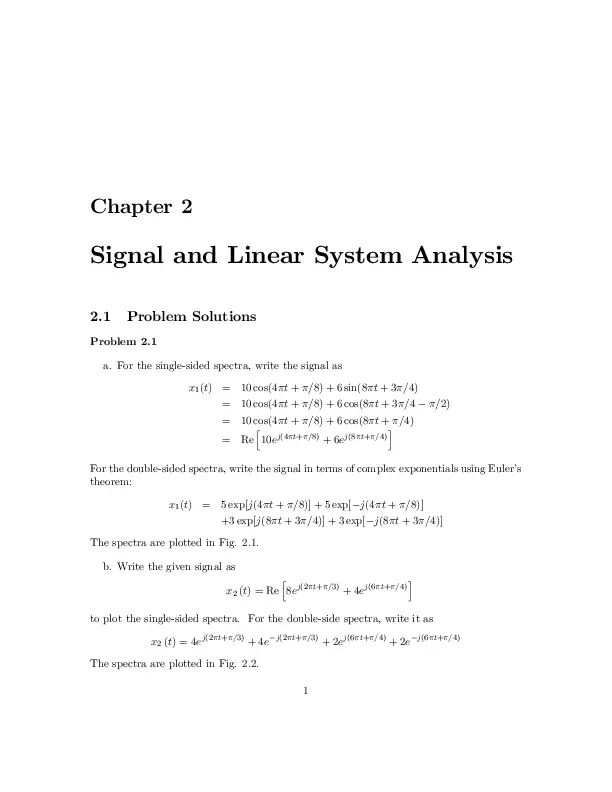
Chapter 2 Signal and Linear System Analysis 2.1 Problem Solutions Problem 2.1 a. For the single-sided spectra, write the signal as x1 (t) = 10 cos(4 t + =8) + 6 sin(8 t + 3 =4) = 10 cos(4 t + =8) + 6 cos(8 t + 3 =4 =2) = 10 cos(4 t + =8) + 6 cos(8 t + =4) i h = Re 10ej(4 t+ =8) + 6ej(8 t+ =4) For the double-sided spectra, write the signal in terms of complex exponentials using Eulerโ€™s theorem: x1 (t) = 5 exp[j(4 t + =8)] + 5 exp[ j(4 t + =8)] +3 exp[j(8 t + 3 =4)] + 3 exp[ j(8 t + 3 =4)] The spectra are plotted in Fig. 2.1. b. Write the given signal as h i x2 (t) = Re 8ej(2 t+ =3) + 4ej(6 t+ =4) to plot the single-sided spectra. For the double-side spectra, write it as x2 (t) = 4ej(2 t+ =3) + 4e j(2 t+ =3) + 2ej(6 t+ =4) + 2e j(6 t+ =4) The spectra are plotted in Fig. 2.2. 1 2 CHAPTER 2. SIGNAL AND LINEAR SYSTEM ANALYSIS c. Change the sines to cosines by subtracting =2 from their arguments to get x3 (t) = 2 cos (4 t + =8 =2) + 12 cos (10 t = 2 cos (4 t 3 =8) + 12 cos (10 t h i = Re 2ej(4 t 3 =8) + 12ej(10 t =2) =2) =2) = ej(4 t 3 =8) + e j(4 t 3 =8) + 6ej(10 t =2) + 6e j(10 t =2) Spectral plots are given in Fig. 2.3. d. Use a trig identity to write 3 sin (18 t + =2) = 3 cos (18 t) and get x4 (t) = 2 cos (7 t + =4) + 3 cos (18 t) i h = Re 2ej(7 t+ =4) + 3ej18 t = ej(7 t+ =4) + e j(7 t+ =4) + 1:5ej18 t + 1:5e j18 t From this it is seen that the singe-sided amplitude spectrum consists of lines of amplitudes 2 and 3 at frequencies of 3.5 and 9 Hz, respectively, and the phase spectrum consists of a line of height =4 at 3.5 Hz. The double-sided amplitude spectrum consists of lines of amplitudes 1, 1, 1.5, and 1.5 at frequencies of 3.5, -3.5, 9, and -9 Hz, respectively. The double-sided phase spectrum consists of lines of heights =4 and =4 at frequencies 3.5 Hz and 3:5 Hz, respectively. e. Use sin (2 t) = cos (2 t =2) to write x5 (t) = 5 cos (2 t h = Re 5ej(2 t = 2:5ej(2 t =2) + 4 cos (5 t + =4) i =2) + 4ej(5 t+ =4) =2) + 2:5e j(2 t =2) + 2ej(5 t+ =4) + 2e j(5 t+ =4) From this it is seen that the singe-sided amplitude spectrum consists of lines of amplitudes 5 and 4 at frequencies of 1 and 2.5 Hz, respectively, and the phase spectrum consists of lines of heights =2 and =4 at 1 and 2.5 Hz, respectively. The double-sided amplitude spectrum consists of lines of amplitudes 2.5, 2.5, 2, and 2 at frequencies of 1, -1, 2.5, and -2.5 Hz, respectively. The double-sided phase spectrum consists of lines of heights =2, =2, =4, and =4 at frequencies of 1, -1, 2.5, and -2.5 Hz, respectively. 2.1. PROBLEM SOLUTIONS 3 Single sided Double sided 6 8 Amplitude Amplitude 10 6 4 4 2 2 0 0 1 2 3 f, Hz 4 0 -5 5 0 f, Hz 5 0 f, Hz 5 0.5 0.6 Phase, rad Phase, rad 0.8 0.4 0.2 0 -0.5 0 0 1 2 3 f, Hz 4 5 f. Use sin (10 t + =6) = cos (10 t + =6 -5 =2) = cos (10 t x6 (t) = 3 cos (4 t + =8) + 4 cos (10 t =3) i h = Re 3ej(4 t+ =8) + 4ej(10 t =3) = 1:5ej(4 t+ =8) + 1:5e j(4 t+ =8) + 2ej10 t =3) to write =3) + 2e j(10 t =3) From this it is seen that the singe-sided amplitude spectrum consists of lines of amplitudes 3 and 4 at frequencies of 2 and 5 Hz, respectively, and the phase spectrum consists of lines of heights =8 and =3 at 2 and 5 Hz, respectively. The double-sided amplitude spectrum consists of lines of amplitudes 1.5, 1.5, 2, and 2 at frequencies of 2, -2, 5, and -5 Hz, respectively. The double-sided phase spectrum consists of lines of heights =8, =8, =3, and =3 at frequencies of 2, -2, 5, and -5 Hz, respectively. 4 CHAPTER 2. SIGNAL AND LINEAR SYSTEM ANALYSIS Single sided Double sided 5 8 6 Amplitude Amplitude 4 4 2 0 2 1 0 1 2 f, Hz 3 0 -4 4 -2 0 f, Hz 2 4 -2 0 f, Hz 2 4 1 Phase, rad 1 Phase, rad 3 0.5 0 0.5 0 -0.5 -1 0 1 2 f, Hz 3 4 -4 2.1. PROBLEM SOLUTIONS 5 Single sided Double sided 6 Amplitude Amplitude 10 5 0 0 2 4 4 2 0 6 -5 0 f, Hz 5 -5 0 f, Hz 5 f, Hz 0 Phase, rad Phase, rad 1 -0.5 -1 0 -1 -1.5 0 2 4 f, Hz 6 6 CHAPTER 2. SIGNAL AND LINEAR SYSTEM ANALYSIS Problem 2.2 By noting the amplitudes and phases of the various frequency components from the plots, the result is x(t) = 4ej(8 t+ =2) + 4e j(8 t+ =2) + 2ej(4 t = 8 cos (8 t + =2) + 4 cos (4 t = 8 sin (8 t) + 4 cos (4 t =4) + 2e j(4 t =4) =4) =4) Problem 2.3 a. Not periodic because f1 = 1= Hz and f2 = 3 Hz are not commensurable. b. Periodic. To โ€ฆnd the period, note that 30 6 = 3 = n1 f0 and = 15 = n2 f0 2 2 Therefore 15 n2 = 3 n1 Hence, take n1 = 1, n2 = 5; and f0 = 3 Hz (we want the largest possible value for f0 with n1 and n2 integer-valued). c. Periodic. Using a similar procedure as used in (b), we โ€ฆnd that n1 = 4, n2 = 21; and f0 = 0:5 Hz. d. Periodic. Using a similar procedure as used in (b), we โ€ฆnd that n1 = 4, n2 = 7; n3 = 11; and f0 = 0:5 Hz. e. Periodic. We โ€ฆnd that n1 = 17, n2 = 18; and f0 = 0:5 Hz. f. Periodic. We โ€ฆnd that n1 = 2, n2 = 3; and f0 = 0:5 Hz. g. Periodic. We โ€ฆnd that n1 = 7, n2 = 11; and f0 = 0:5 Hz. h. Not periodic. The frequencies of the separate terms are incommensurable. i. Periodic. We โ€ฆnd that n1 = 19, n2 = 21; and f0 = 0:5 Hz. j. Periodic. We โ€ฆnd that n1 = 6, n2 = 7; and f0 = 0:5 Hz. 2.1. PROBLEM SOLUTIONS 7 Problem 2.4 a. The single-sided amplitude spectrum consists of a single line of amplitude 5 at 6 Hz and the phase spectrum consists of a single line of height =6 rad at 6 Hz. The double-sided amplitude spectrum consists of lines of amplitude 2.5 at frequencies 6 Hz. The double -sided phase spectrum consists of a line of height =6 at -6 Hz and a line of height =6 at 6 Hz. b. Write the signal as x2 (t) = 3 cos(12 t =2) + 4 cos(16 t) From this it is seen that the single-sided amplitude spectrum consists of lines of heights 3 and 4 at frequencies 6 and 8 Hz, respectively, and the single-sided phase spectrum consists of a line of height =2 radians at frequency 6 Hz (the phase at 8 Hz is 0). The doublesided amplitude spectrum consists of lines of height 1.5 and 2 at frequencies of 6 and 8 Hz, respectively, and lines of height 1.5 and 2 at frequencies 6 and 8 Hz, respectively. The double-sided phase spectrum consists of a line of height =2 radians at frequency 6 Hz and a line of height =2 radians at frequency 6 Hz. c. Use the trig identity cos x cos y = 0:5 cos (x + y) + 0:5 cos (x y) to write x3 (t) = 2 cos 20 t + 2 cos 4 t From this we see that the single-sided amplitude spectrum consists of lines of height 2 at 2 and 10 Hz, and the single-sided phase spectrum is 0 at these frequencies. The double-sided amplitude spectrum consists of lines of height 1 at frequencies of 10, 2, 2, and 10 Hz. The double-sided phase spectrum is 0. d. Use trig identies to get x4 (t) = 4 sin (2 t) [1 + cos (10 t)] = 4 sin (2 t) 2 sin (8 t + ) + 2 sin (12 t) = 4 cos (2 t h = Re 4ej(2 t =2) + 2 cos (8 t + =2) + 2 cos (12 t i =2) + 2ej(8 t+ =2) + 2ej(12 t =2) = 2ej(2 t =2) + 2e j(2 t =2) =2) + ej(8 t+ =2) + e j(8 t+ =2) + ej(12 t =2) + e j(12 t From this we see that the single-sided amplitude spectrum consists of lines of heights 4, 2, and 2 at frequencies 1, 4, and 6 Hz, respectively and the single-sided phase spectrum is =2 radians at 1 and 6 Hz and =2 radians at 4 Hz. The double-sided amplitude spectrum =2) 8 CHAPTER 2. SIGNAL AND LINEAR SYSTEM ANALYSIS consists of lines of height 2 at frequencies of 1 and 1 Hz and of height 1 at frequencies of 4, -4, 6, and -6 Hz. The double-sided phase spectrum is =2 radians at -1, 4, and -6 Hz and =2 radians at 1, -4, and 6 Hz. e. Clearly, from the form of the cosine sum, the single-sided amplitude spectrum has lines of heights 1 and 7 at frequencies of 3 and 15 Hz, respectively. The single-sided phase spectrum is zero. The double-sided amplitude spectrum has lines of heights 0.5, 0.5, 3.5, and 3.5 at frequencies of 3, -3, 15, and -15 Hz, respectfully. The double-sided phase spectrum is zero. f. The single-sided amplitude spectrum has lines of heights 1 and 9 at frequencies of 2 and 10.5 Hz, respectively. The single-sided phase spectrum is =2 radians at 10.5 Hz and 0 otherwise. The double-sided amplitude spectrum has lines of heights 0.5, 0.5, 4.5, and 4.5 at frequencies of 2, -2, 10.5, and -10.5 Hz, respectfully. The double-sided phase spectrum is =2 radians at -10.5 Hz and =2 radians at 10.5 Hz and 0 otherwise. g. Convert the sine to a cosine by subtracting =2 from its argument. It then follows that the single-sided amplitude spectrum is 2, 1, and 6 at frequencies of 2, 3, and 8.5 Hz and 0 otherwise. The single-sided phase spectrum is =2 radians at 8.5 Hz and 0 otherwise. The double-sided amplitude spectrum is 1, 1, 0.5, 0.5, 3, and 3 at frequencies of 2, 2, 3, 3 8:5, and 8.5 Hz, respectively, and 0 otherwise. The double-sided phase spectrum is =2 radians at a frequency of 8:5 Hz and =2 radians at a frequency of 8.5 Hz. It is 0 otherwise. Problem 2.5 a. This function has area Area = Z1 1 = Z1 sin( u) 2 du = 1 ( u) sin( t= ) 2 dt ( t= ) 1 1 where a tabulated integral has been used for sinc2 u. A sketch shows that no matter how small is, the area is still 1. With ! 0; the central lobe of the function becomes narrower and higher. Thus, in the limit, it approximates a delta function. 2.1. PROBLEM SOLUTIONS 9 b. The area for the function is Z1 Area = 1 exp( t= )u (t) dt = 1 Z1 exp( u)du = 1 0 A sketch shows that no matter how small is, the area is still 1. With ! 0; the function becomes narrower and higher. Thus, in the limit, it approximates a delta function. R 1 R1 c. Area = (1 jtj = ) dt = As ! 0, the function becomes 1 (t) dt = 1. narrower and higher, so it approximates a delta function in the limit. Problem 2.6 1 (t) to write (2t 5) = a. Make use of the formula (at) = jaj 1 5 t 2 and use the sifting property of the -function to get 2 Ia = 1 2 5 2 2 + 1 exp 2 2 5 2 = [2 (t 5=2)] = 25 1 + exp [ 5] = 3:1284 8 2 b. Impulses at 10, 5, 0, 5, 10 are included in the integral. Use the sifting property after writing the expression as the sum of โ€ฆve integrals to get Ib = ( 10)2 + 1 + ( 5)2 + 1 + 02 + 1 + 52 + 1 + 102 + 1 = 255 c. Matching coeยข cients of like derivatives of -functions on either side of the equation gives A = 5, B = 10, and C = 3. d. Use I = 14 1 (at) = jaj (t) to write e 4 ( 3=4) + tan 10 (4t + 3) = 14 3 4 = 14 e3 t + 34 . The integral then becomes + tan ( 7:5 ) = 9:277 1013 . e. Use property 5 of the unit impulse function to get d2 d Ie = ( 1)2 2 cos 5 t + e 3t t=2 = 5 sin 5 t 3e 3t t=2 dt dt h i = (5 )2 cos 5 t + 9e 3t = (5 )2 cos 10 + 9e 6 = 246:73 t=2 10 CHAPTER 2. SIGNAL AND LINEAR SYSTEM ANALYSIS Problem 2.7 (a), (c), and (e) are periodic. Their periods are 2 s (fundamental frequency of 0.5 Hz), 2 s, and 3 s, respectively. The waveform of part (c) is a periodic train of triangles, each 2 units wide, extending from -1 to 1 spaced by 2 s ((b) is similar except that it is zero for t < 1 thus making it aperiodic). Waveform (d) is aperiodic because the frequencies of its two components are incommensurable. The waveform of part (e) is a doubly-inโ€ฆnite train of square pulses, each of which is one unit high and one unit wide, centered at ; 6; 3; 0; 3; 6; . Waveform (f) is identical to (e) for t 1=2 but 0 for t < 1=2 thereby making it aperiodic. Problem 2.8 a. The result is x(t) = cos (6 t)+2 cos (10 t j(10 t =2) 1 1 + e j6 t + ej6 t + ej(10 t 2 2 =2) =2) = Re e j6 t +Re 2e h = Re e j6 t + 2e j(10 t b. The result is x(t) = e j(10 t =2) c. The single-sided amplitude spectrum consists of lines of height 1 and 2 at frequencies of 3 and 5 Hz, respectively. The single-sided phase spectrum consists of a line of height =2 at frequency 5 Hz. The double-sided amplitude spectrum consists of lines of height 1, 1/2, 1/2, and 1 at frequencies of 5; 3; 3; and 5 Hz, respectively. The double-sided phase spectrum consists of lines of height =2 and =2 at frequencies of 5 and 5 Hz, respectively. Problem 2.9 a. Power. Since it is a periodic signal, we obtain Z T0 Z T0 1 1 2 P1 = 4 cos (4 t + 2 =3) dt = 2 [1 + cos (8 t + 4 =3)] dt = 2 W T0 0 T0 0 where T0 = 1=2 s is the period. The cosine in the above integral integrates to zero because the interval of integratation is two periods. b. Energy. The energy is E2 = Z 1 1 e 2 t 2 u (t)dt = Z 1 0 e 2 t dt = 1 J 2 =2) i 2.1. PROBLEM SOLUTIONS 11 c. Energy. The energy is E3 = Z 1 e 2 t 2 u ( t)dt = Z 0 e2 t dt = 1 1 1 J 2 d. Energy. The energy is E4 = = = Z T dt 1 = lim 2 2 + t2 ) T !1 ( T lim T !1 1 lim T !1 1h 2 2 T t tan 1 i = lim dt 1 + (t= )2 T 1 tan 1 (T = ) T !1 T = Z T tan 1 ( T = ) J e. Energy. Since it is the sum of x2 (t) and x3 (t), its energy is the sum of the energies of these two signals, or E5 = 1= J. f. Energy. The energy is E6 = = = = = = lim T !1 lim T !1 lim T !1 lim T !1 lim Z T h T Z T h t u (t) (t 1) e e 2 t u2 (t) e 2 t dt e 1) (t 1) e i2 dt e 2 t dt 2 + Z T e 1 2 (t 1) dt + 0 e 2 t dt0 + 0 e 2 2 +e 0 1 1 = 2 1 1) + e 2 (t 1) u2 (t u (t) u (t 1 8 0 < e 2 t T e 2 u (t e Z T 0 Z T t e T Z T T !1 : 1 2 e Z T 0 t0 1 e 2 T 1 e 2 2 0 J e 2 (t 1) dt 1 Z T 1 t0 T 0 0 e 2 t dt0 9 1= ; i 1) dt 12 CHAPTER 2. SIGNAL AND LINEAR SYSTEM ANALYSIS Problem 2.10 a. Power. Since the signal is periodic with period 2 =!, we have ! P = 2 Z 2 =! 0 ! A jsin (!t + )j dt = 2 2 2 Z 2 =! 0 A2 f1 2 cos [2 (!t + )]g dt = A2 W 2 b. Neither. The energy calculation gives Z T Z T (A )2 dt (A )2 dt p p p dt ! 1 E = lim dt = lim 2 + t2 T !1 T !1 + jt jt T T The power calculation gives 1 P = lim T !1 2T Z T (A )2 dt (A )2 p ln dt = lim 2 + t2 T !1 2T T c. Energy: E= Z 1 0 1 A t exp ( 2t= ) dt = A2 8 2 2 r 2 p 1 + T 2= 2 p 1 + 1 + T 2= 2 1+ ! =0W W (use a table of integrals) d. Energy: This is a "top hat" pulse which is height 2 for jtj =2, height 1 for =2 < jtj , and 0 everywhere else. Making use of the even symmetry about t = 0, the energy is ! Z =2 Z E=2 22 dt + 12 dt = 5 J 0 =2 e. Energy. The signal is a "house" two units wide and one unit up to the eves with a equilateral triangle for a roof. Because of symmetry, the energy calculation need be carried out for positive t and doubled. The calculation is Z 1 1 2 2 2 8 14 E=2 (2 t)2 dt = (2 t)3 = + = J 3 3 3 3 0 0 f. Power. Since the two terms are harmonically related, we may add their respective powers and get A2 B 2 P = + W 2 2 2.1. PROBLEM SOLUTIONS 13 Problem 2.11 a. Using the fact that the power contained in a sinusoid is its amplitude squared divided by 2, we get 22 P = =2W 2 b. This is a periodic train of "box cars" 3 units high, 2 units wide, and occurring every 4 units (period of 4 seconds). The power calculation is Z 1 1 2 32 2 P = 3 dt = = 4:5 W 4 1 4 c. This is a train of triangles 1 unit high, 4 s wide, and occuring every 6 s. Using the waveform period centered at 0, the power calculation is 1 P = 6 Z 2 1 2 t 2 2 dt = 12 63 1 t 2 3 2 = 0 2 W 9 d. This is a train of "houses" each of which is 2 s wide, 1 unit high to the eves, with an isoceles triangle on top for the roof. They are separated by 4 s (the period). Using the even symmetry of each house, the power calculation is 2 Pd = 4 Z 1 2 (2 t) dt = 0 1 (2 t)3 2 3 1 = 0 1 2 1 3 23 3 = 7 W 6 Problem 2.12 a. The energy is E = Z 1 0 = 36 6e Z 1 ( 3+j4 )t e 6t dt = 0 2 dt = 36 Z 1 e( 3+j4 )t e( 3 j4 )t dt 0 1 e 6t 36 =6J 6 0 The power is 0 W. b. This signal is a "top hat" pulse which is 2 for 2 t 4, 1 for 0 t < 2 and 4 < t and 0 everywhere else. It is clearly an energy signal with energy E=2 12 + 2 22 + 2 12 = 12 J 6, 14 CHAPTER 2. SIGNAL AND LINEAR SYSTEM ANALYSIS Its power is 0 W. c. This is a power signal with power Z T Z 1 49 T 49 j6 t j6 t P = lim 49e e u (t) dt = lim dt = = 24:5 W T !1 2T T !1 2T 0 2 T Its energy is inโ€ฆnite. 2 d. This is a periodic signal with power P = 22 = 2 W. Its energy is inโ€ฆnite. e. This is neither an energy nor a power signal. Its energy is inโ€ฆnite and its power is 1 T !1 2T P = lim Z T 1 t3 T !1 2T 3 T t2 dt = lim T 1 2T 3 !1 T !1 2T 3 = lim T f. This is neither an energy nor a power signal. Its energy is Z 1 t 1 dt = ln (t)j1 E= 1 !1 1 and its power is 1 P = lim T !1 2T Problem 2.13 Z T 1 ln (t)j1 1 =0 T !1 2T t 1 dt = lim 1 a. This is a cosine burst from t = 6 to t = 6 seconds. The energy is E1 = R6 2 0 12 + 12 cos (12 t) dt = 6 J R6 6 cos b. The energy is E2 = Z 1h 1 = 2 e e jtj=3 2t=3 2=3 i2 dt = 2 Z 1 e 2t=3 dt (by even symmetry) 0 1 =3J 0 Since the result is โ€ฆnite, this is an energy signal. c. The energy is E3 = Z 1 1 f2 [u (t) u (t 2 8)]g dt = Z 8 0 4dt = 32 J 2 (6 t) dt = 2.1. PROBLEM SOLUTIONS 15 Since the result is โ€ฆnite, this is an energy signal. d. Note that r (t) , Z t u( )d = 1 0; t < 0 t; t 0 which is called the unit ramp. Thus the given signal is a triangle between 0 and 20. The energy is Z 1 Z 10 2 2000 10 2 E4 = [r (t) 2r (t 10) + r (t 20)] dt = 2 t2 dt = t3 0 = J 3 3 1 0 where the last integral follows because the integrand is a symmetrical triangle about t = 10. Since the result is โ€ฆnite, this is an energy signal. Problem 2.14 a. This is a cosine burst nonzero between 0 and 2 seconds. Its power is 0. Its energy is Z Z 2 1 2 2 [1 + cos (20 t)] dt = 1 J E1 = cos (10 t) dt = 2 0 0 b. This is a periodic sequence of triangles of period 3 s. Its energy is inโ€ฆnite. Its power is Z 2 2 4 P2 = (1 t=2)2 dt = J 3 0 9 c. This is an energy signal. Its power is 0. Using evenness of the integrand, its energy is Z 1 Z 1 Z 1 2t 2 2t E3 = 2 e cos (2 t) dt = e dt + e 2t cos (4 t) dt 0 = 0 0 1 2 + J 2 4 + 16 2 . d. This is an energy signal. Its energy is E4 = 2 Z 1 0 (2 t)2 dt = 2 (2 3 1 t)3 = 0 14 J 3 16 CHAPTER 2. SIGNAL AND LINEAR SYSTEM ANALYSIS Problem 2.15 a. Use the exponential representation of the sine to get the Fourier coeยข cients as (note that the period = 12 f10 ). x1 (t) = ej2 f0 t e j2 f0 t 2j from which we โ€ฆnd that X 1 = X1 = 2 1 e j4 f0 t 4 = 2 + ej4 f0 t 1 1 ; X0 = 4 2 All other coeยข cients are zero. b. Use the exponential representations of the sine and cosine to get 1 1 1 x2 (t) = ej2 f0 t + e j2 f0 t + ej4 f0 t 2 2 2j 1 j4 f0 t e 2j Therefore, the Fourier coeยข cients for this case are X 1 = X1 = 1 1 and X2 = X 2 = 2 2j All other coeยข cients are zero. c. Use a trig identity to write this signal as x3 (t) = 1 1 sin 8 f0 t = ej8 f0 t 2 4j 1 j8 f0 t e 4j The fundamental frequency is 4f0 Hz. From this it follows that the Fourier coeยข cients are X1 = X 1 = 1 4j All other coeยข cients are zero. d. Use trig identities and the exponential forms of cosine to write this signal as x4 (t) = = 1 3 cos 2 f0 t + cos 6 f0 t 4 4 3 j2 f0 t 3 j2 f0 t 1 j6 f0 t 1 j6 f0 t + e + e + e e 8 8 8 8 2.1. PROBLEM SOLUTIONS 17 The fundamental frequency is f0 Hz. It follows that the Fourier coeยข cients for this case are 3 1 X 1 = X1 = ; X 3 = X3 = 8 8 All other Fourier coeยข cients are zero. e. Use trig identies to write x5 (t) = = 1 1 1 sin (2 f0 t) sin (6 f0 t) + sin (10 f0 t) 2 4 4 1 j2 f0 t 1 j2 f0 t 1 j6 f0 t 1 1 e e e + e j6 f0 t + ej10 f0 t 4j 4j 8j 8j 8j 1 j10 f0 t e 8j The fundamental frequency is f0 Hz. It follows that the Fourier coeยข cients for this case are j j j X 1 = X1 = ; X 3 = X3 = ; X 5 = X5 = 4 8 8 All other Fourier coeยข cients are zero. f. Use trig identities to write x6 (t) = = 1 1 1 cos (6 f0 t) cos ( f0 t) cos (11 f0 t) 2 4 4 1 j6 f0 t 1 j6 f0 t 1 j f0 t 1 j f0 t 1 j11 f0 t e + e e e e 4 4 8 8 8 1 j11 f0 t e 8 The fundamental frequency is f0 =2 Hz. It follows that the Fourier coeยข cients for this case are 1 1 1 X 1 = X1 = ; X 12 = X12 = ; X 22 = X22 = 8 4 8 All other Fourier coeยข cients are zero. Problem 2.16 The expansion interval is T0 = 4 so that f0 = 1=4 Hz. The Fourier coeยข cients are Z Z 2 2 2 1 2 2 jn( =2)t Xn = 2t e dt = t (cos n t=2 j sin n t=2) dt = 4 2 4 2 Z 2 2 2 n t dt = 2t cos 4 0 2 which follows by the oddness of the second integrand and the eveness of the โ€ฆrst integrand. Let u = n t=2 to obtain the form Z 2 3 n 2 16 Xn = u cos u du = ( 1)n n 6= 0 (use a table of integrals) 2 n (n ) 0 18 CHAPTER 2. SIGNAL AND LINEAR SYSTEM ANALYSIS If n = 0, the integral for the coeยข cients is 1 X0 = 4 Z 2 2t2 dt = 2 8 3 The Fourier series is therefore 8 x (t) = + 3 1 X ( 1)n n= 1; n6=0 16 jn( =2)t e (n )2 Problem 2.17 Parts (a) through (c) were discussed in the text. For (d), break the integral for Xn up into a part for t 0. Then use the odd half-wave symmetry condition. The development follows: Xn = = = 1 T0 1 T0 1 T0 1 = T0 ( = “Z T0 =2 x (t) e j2 nf0 t dt + T0 =2 x (t) e j2 nf0 t dt + 0 “Z Z T0 =2 # x t0 + T0 =2 e j2 nf0 (t0 +T0 =2) 0 T0 =2 x (t) e j2 nf0 t dt 0 “Z x (t) e j2 nf0 t dt T0 =2 0 “Z Z 0 Z T0 =2 0 x t e j2 nf0 t0 jn x (t) e j2 nf0 t dt ( 1) n 0 0; n even R T0 =2 2 x (t) e j2 nf0 t dt; n odd T0 0 Z T0 =2 0 0 x t e dt ; t0 = t + T0 =2 dt ; f0 = 1=T0 0 T0 =2 # # j2 nf0 t0 dt # 2.1. PROBLEM SOLUTIONS 19 Problem 2.18 This is a matter of integration. Only the solution for part (b) will be given here. integral for the Fourier coeยข cients is Xn = = = = = = Z T0 =2 A sin (! 0 t) e dt = ej!0 t e j!0 t e jn!0 t dt 2jT0 0 0 # “Z Z T0 =2 T0 =2 A e j(1+n)!0 t dt ej(1 n)!0 t dt 2jT0 0 0 2 3 T0 =2 T0 =2 j(1 n)! t j(1+n)! t 0 0 A 4 e e 5 2jT0 j (1 n) ! 0 j (1 + n) ! 0 0 0 ” # A ej(1 n) 1 e j(1+n) 1 + ; n 6= 1 (! 0 T0 =2 = ) 4 1 n 1+n A T0 A 4 ( Z T0 =2 The jn! 0 t ( 1)n + 1 ( 1)n + 1 + ; n 6= 1 n 1+n 0; n odd and n 6= A ; n even (1 n2 ) 1 1 For n = 1, the integral is X1 = A 2jT0 = A 2jT0 Z T0 =2 ej!0 t e j!0 t e j!0 t dt 0 Z T0 =2 1 e j2!0 t dt = 0 jA =X 1 4 This is the same result as given in Table 2.1. Problem 2.19 a. Use Parsevalโ€™s theorem to get Pjnf0 j 1= = N X n= N jXn j2 = N X n= N A T0 2 sinc2 (nf0 ) where N is an appropriately chosen limit on the sum. We are given that only frequences for which jnf0 j 1= are to be included. This is the same as requiring that jnj 1= ( f0 ) = 20 CHAPTER 2. SIGNAL AND LINEAR SYSTEM ANALYSIS T0 = = 2: Also, for a pulse train, Ptotal = A2 =T0 and, in this case, Ptotal = A2 =2: Thus 2 Pjnf0 j 1= Ptotal = 2 X A2 n= 2 A 2 2 sinc2 (nf0 ) 2 = 1 X sinc2 (nf0 ) 2 n= 2 = = b. In this case, jnj Pjnf0 j 1= Ptotal c. In this case, jnj Pjnf0 j 1= Ptotal = 1 1 + 2 sinc2 (1=2) + sinc2 (1) 2″ # 1 2 2 1+2 = 0:9053 2 5, Ptotal = A2 =5, and 5 1 X = sinc2 (n=5) 5 n= 5 h io 1n = 1 + 2 (0:9355)2 + (0:7568)2 + (0:5046)2 + (0:2339)2 5 = 0:9029 10, Ptotal = A2 =10, and 10 1 X sinc2 (n=10) 10 n= 10 1 1+2 10 = 0:9028 = d. In this case, jnj (0:9836)2 + (0:9355)2 + (0:8584)2 + (0:7568)2 + (0:6366)2 + (0:5046)2 + (0:3679)2 + (0:2339)2 + (0:1093)2 20, Ptotal = A2 =20, and Pjnf0 j 1= Ptotal = = 20 1 X sinc2 (n=20) 20 n= 20 ( ) 20 X 1 1+2 sinc2 (n=20) 20 n=1 = 0:9028 2.1. PROBLEM SOLUTIONS 21 Problem 2.20 a. The integral for Yn is Z Z T0 1 1 jn! 0 t y (t) e dt = x (t Yn = T0 T0 T0 0 Let t0 = t t0 ) e jn!0 t dt; ! 0 = 2 f0 t0 , which results in Z T0 t0 1 0 Yn = x t0 e jn!0 t dt0 e jn!0 t0 = Xn e j2 nf0 t0 T 0 t0 b. Note that y (t) = A cos ! 0 t = A sin (! 0 t + =2) = A sin [! 0 (t + =2! 0 )] Thus, t0 in the theorem proved in part (a) here is can be expressed as 1 sin (! 0 t) = ej!0 t 2j =2! 0 . By Eulerโ€™s theorem, a sine wave 1 j!0 t e 2j 1 Its Fourier coeยข cients are thereforeX1 = 2j and X 1 = proved in part (a), we multiply these by the factor e jn!0 t0 = e jn!0 ( =2! 0 ) 1 2j . According to the theorem = ejn =2 For n = 1, we obtain Y1 = For n = 1 j =2 1 e = 2j 2 1, we obtain 1 j =2 1 e = 2j 2 which gives the Fourier series representation of a cosine wave as Y 1= 1 1 y (t) = ej!0 t + e j!0 t = cos ! 0 t 2 2 We could have written down this Fourier representation directly by using Eulerโ€™s theorem. Problem 2.21 a. Use the Fourier series of a square wave (specialize the Fourier series of a pulse train) with A = 1 and t = 0 to obtain the series 1= 4 1 1 1 + 3 5 1 + 7 22 CHAPTER 2. SIGNAL AND LINEAR SYSTEM ANALYSIS Multiply both sides by 4 to get the series in the problem statement. Hence, the sum is 4 . b. Use the Fourier series of a triangular wave as given in Table 2.1 with A = 1 and t = 0 to obtain the series 1= + 4 4 4 4 4 4 + + 2+ 2+ 2+ + 25 2 9 2 9 25 2 2 Multiply both sides by 8 to get the series in given in the problem. Hence, its sum is 2 8 . Problem 2.22 a. In the expression for the Fourier series of a pulse train (Table 2.1), let t0 = and = T0 =4 to get n nf0 A exp j Xn = sinc 4 4 4 T0 =8 The spectra are shown in Fig. 2.4. b. The amplitude spectrum is the same as for part (a) except that X0 = 3A 4 . Note that this can be viewed as having a sinc-function envelope with zeros at multiples of 3T4 0 . The phase spectrum can be obtained from that of part (a) by subtracting a phase shift of for negative frequencies and adding for postitive frequencies (or vice versa). The Fourier coeยข cients are given by Xn = 3A sinc 4 3n 4 exp j 3 nf0 4 See Fig. 2.4 for amplitude and phase plots. Problem 2.23 a. Use the rectangular pulse waveform of Table 2.1 specialized to xa (t) = 2A t T0 =4 T0 =2 A; jtj < T0 =2 and periodically extended. Hence, from Table 2.1, we have 2AT0 =2 nT0 =2 2 nT0 =4 sinc exp j T0 T0 T0 = Asinc (n=2) exp ( j n=2) ; n 6= 0 sin (n =2) = A exp ( j n=2) ; n 6= 0 n =2 XnA = 2.1. PROBLEM SOLUTIONS 23 Part (a) Part (b) 0.6 Amplitude Amplitude 0.6 0.4 0.2 0 -5 0 f, Hz 0.2 0 5 -5 0 f, Hz 5 -5 0 f, Hz 5 2 Phase, rad 2 Phase, rad 0.4 0 -2 0 -2 -5 0 f, Hz 5 24 CHAPTER 2. SIGNAL AND LINEAR SYSTEM ANALYSIS where the superscript A refers to xA (t). The dc component is 0 so X0A = 0. The Fourier coeยข cients are therefore X0A = 0 X1A = j2A= ; X A1 = j2A= X2A = 0 = X A2 X3A = j2A=3 ; X A3 = j2A=3 b. Note that xA (t) = dxB (t) dt where A = T2B = 4B T0 obtained from matching the amplitude of xA (t) with the slope of 0 =2 xB (t) or B = T40 A. The relationship between spectral components is therefore XnA = (jn! 0 ) XnB = j2 nf0 XnB or XnB = XnA T0 XnA = j2 nf0 j2 n where the superscript A refers to xA (t) and B refers to xB (t). For example, X1B = j2A= = j2 f0 2B 2 = X B1 Problem 2.24 a. This is a decaying exponential starting at t = 0 and its Fourier transform is Z 1 Z 1 X1 (f ) = A e t= e j2 f t dt = A e (1= +j2 f )t dt 0 0 (1= +j2 f )t = Ae 1= + j2 f = A 1 + j2 f 1 = 0 A 1= + j2 f 2.1. PROBLEM SOLUTIONS 25 b. Since x2 (t) = x1 ( t) we have, by the time reversal theorem, that X2 (f ) = X1 (f ) = X1 ( f ) A = 1 j2 f c. Since x3 (t) = x1 (t) x2 (t) we have, after some simpliโ€ฆcation, that X3 (f ) = X1 (f ) X2 (f ) A A = 1 + j2 f 1 j2 f j4A f = 1 + (2 f )2 d. Since x4 (t) = x1 (t) + x2 (t) we have, after some simpliโ€ฆcation, that X4 (f ) = X1 (f ) + X2 (f ) A A = + 1 + j2 f 1 j2 f 2A = 1 + (2 f )2 This is the expected result since x4 (t) is really a double-sided decaying exponential. e. By part a and the delay theorem X5 (f ) = X1 (f ) e j10 f = A e j10 f 1 + j2 f f. By parts a and e and superposition h X6 (f ) = X1 (f ) 1 i A e j10 f = 1 e j10 f 1 + j2 f Problem 2.25 a. Using a table of Fourier transforms and the time reversal theorem, the Fourier transform of the given signal is X (f ) = 1 + j2 f 1 j2 f 26 CHAPTER 2. SIGNAL AND LINEAR SYSTEM ANALYSIS Note that x (t) ! sgn(t) in the limit as transform as ! 0, we deduce that F [sgn (t)] = ! 0. 1 j2 f Taking the limit of the above Fourier 1 1 = j2 f j f b. Using the given relationship between the unit step and the signum function and the linearity property of the Fourier transform, we obtain F [u (t)] = = 1 1 F [sgn (t)] + F [1] 2 2 1 1 + (f ) j2 f 2 c. The same result as obtained in part (b) is obtained. Problem 2.26 a. One diยคerentiation gives dxa (t) = dt (t 0:5) (t 2:5) Two diยคerentiations give d2 xa (t) = (t) dt2 (t 1) (t 2) + (t + 3) Application of the diยคerentiation theorem of Fourier transforms gives (j2 f )2 Xa (f ) = 1 = 1 e j2 f ej3 f ej f = 2 (cos 3 f 1 e j4 f + 1 e j6 f e j f + e j3 f e j3 f cos f ) e j3 f where the time delay theorem and the Fourier transform of a unit impulse have been used. Dividing both sides by (j2 f )2 , we obtain Xa (f ) = cos f cos 3 f j3 f 2 (cos 3 f cos f ) e j3 f = e 2 2 2f 2 (j2 f ) 2.1. PROBLEM SOLUTIONS 27 Use the trig identity sin2 x = 12 1 2 cos 2x or cos 2x = 1 2 sin2 x to rewrite this result as 2 sin2 (0:5 f ) 1 + 2 sin2 (1:5 f ) j3 f e 2 2f 2 sin2 (0:5 f ) + sin2 (1:5 f ) j3 f = e 2f 2 sin2 (1:5 f ) j3 f sin2 (0:5 f ) j3 f = e e 2f 2 2f 2 " # 2 2 sin 1:5 f sin 0:5 f = 1:52 0:52 e j3 f 1:5 f 0:5 f Xa (f ) = = 1 0:52 sinc2 (0:5f ) e j3 f 1:52 sinc2 (1:5f ) This is the same result as would have been obtained by writing t xa (t) = 1:5 1:5 1:5 t 0:5 1:5 0:5 and using the Fourier transform of the triangular pulse along with the superposition and time delay theorems. b. Two diยคerentiations give (sketch dxb (t) =dt to see this) d2 xb (t) = (t) dt2 2 (t 1) + 2 (t 3) (t 4) Application of the diยคerentiation theorem gives (j2 f )2 Xb (f ) = 1 2e j2 f + 2e j6 f e j8 f Dividing both sides by (j2 f )2 , we obtain Xb (f ) = 1 2e j2 f + 2e j6 f 4 2f 2 e j8 f Further manipulation may be applied to this result to convert it to h i Xb (f ) = sinc2 (f ) e j2 f e j6 f h i = sinc2 (f ) ej2 f e j2 f e j4 f = 2j sin (2 f ) sinc2 (f ) e j4 f which would have resulted from Fourier transforming the waveform written as xb (t) = (t 1) (t 3) 28 CHAPTER 2. SIGNAL AND LINEAR SYSTEM ANALYSIS c. Two diยคerentiations give (sketch dxc (t) =dt to see this) d2 xc (t) = (t) dt2 2 (t 1) + 2 (t 2) 2 (t 3) + (t 4) Application of the diยคerentiation theorem gives (j2 f )2 Xc (f ) = 1 2e j2 f + 2e j4 f 2e j6 f + e j8 f Dividing both sides by (j2 f )2 , we obtain Xc (f ) = 2e j2 f + 2e j4 f 2e j6 f + e j8 f (j2 f )2 1 This result may be further arranged to give 2 h Xc (f ) = sinc (f ) e j2 f j6 f +e i = 2 cos (2 f ) sinc2 (f ) e j4 f which would have resulted from Fourier transforming the waveform written as xc (t) = (t 1) + (t 3) d. Two diยคerentiations give (sketch dxd (t) =dt to see this) d2 xd (t) = (t) dt2 2 (t 1) + (t 1:5) + (t 2:5) 2 (t 3) + (t Application of the diยคerentiation theorem gives (j2 f )2 Xd (f ) = 1 2e j2 f + e j3 f + e j5 f 2e j6 f + e j8 f Dividing both sides by (j2 f )2 , we obtain Xd (f ) = 1 2e j2 f + e j3 f + e j5 f (j2 f )2 2e j6 f + e j8 f This result may be further arranged to give h i Xd (f ) = sinc2 (f ) e j2 f + 0:5e j4 f + e j6 f which would have resulted from Fourier transforming the waveform written as xd (t) = (t 1) + 0:5 (t 2) + (t 3) 4) 2.1. PROBLEM SOLUTIONS 29 Problem 2.27 See the solutions to Problem 2.26. Problem 2.28 a. The steps in โ€ฆnding the Fourier transform for (i) are as follows: (t) ! sinc (f ) (t) exp [j4 t] (t 1) exp [j4 (t ! sinc (f 1)] ! sinc (f 2) 2) exp ( j2 f ) The steps in โ€ฆnding the Fourier transform for (ii) are as follows: (t) ! sinc (f ) (t) exp [j4 t] ! sinc (f (t + 1) exp [j4 (t + 1)] ! sinc (f 2) 2) exp (j2 f ) b. The steps in โ€ฆnding the Fourier transform for (i) are as follows: (t) (t (t 1) 1) exp [j4 (t 1)] ! sinc (f ) ! sinc (f ) exp ( j2 f ) = (t 1) exp (j4 t) ! sinc (f 2) exp [ j2 (f 2)] = sinc (f 2) exp ( j2 f ) which follows because exp( jn2 ) = 1 where n is an integer. The steps in โ€ฆnding the Fourier transform for (ii) are as follows: (t) (t + 1) (t + 1) exp [j4 (t + 1)] ! sinc (f ) ! sinc (f ) exp (j2 f ) = (t + 1) exp (j4 t) ! sinc (f 2) exp [j2 (f 2)] = sinc (f 2) exp (j2 f ) 30 CHAPTER 2. SIGNAL AND LINEAR SYSTEM ANALYSIS Problem 2.29 a. The time reversal theorem states that x ( t) so xa (t) ! = ! X ( f ) 6= X (f ) if x (t) is complex, 1 1 1 1 X1 (f ) + X1 ( f ) = sinc (f 2) exp ( j2 f ) + sinc ( f 2 2 2 2 1 1 sinc (f 2) exp ( j2 f ) + sinc (f + 2) exp (j2 f ) 2 2 2) exp (j2 f ) Note that xa (t) = = 1 2 1 2 (t 1) exp [j4 (t 1)] + (t 1) exp (j4 t) + 1 2 1 2 ( t 1) exp [j4 ( t 1)] (t + 1) exp ( j4 t) (by the eveness of (u) ) b. Similarly to (a), we obtain xb (t) 1 1 1 ! X2 (f )+ X2 ( f ) = sinc (f 2 2 2 1 2) exp (j2 f )+ sinc (f + 2) exp ( j2 f ) 2 2.1. PROBLEM SOLUTIONS 31 Problem 2.30 a. The result is X1 (f ) = 2sinc (2f ) exp ( j2 f ) b. The result is X2 (f ) = 2 1 2 f 2 exp ( j2 f ) c. The result is X3 (f ) = 8sinc2 (8f ) exp ( j4 f ) d. The result is X4 (f ) = 4 (4f ) exp ( j6 f ) e. The result is X5 (f ) = 5 = 5 1 2 f 2 f 2 exp ( j2 f ) + 5 1 2 f 2 exp (j2 f ) cos (2 f ) f. The result is X6 (f ) = 16sinc2 (8f ) exp ( j4 f ) + 16sinc2 (8f ) exp (j4 f ) = 32sinc2 (8f ) cos (4 f ) Problem 2.31 a. This is an odd signal, so its Fourier transform is odd and purely imaginary. b. This is an even signal, so its Fourier transform is even and purely real. c. This is an odd signal, so its Fourier transform is odd and purely imaginary. d. This signal is neither even nor odd, so its Fourier transform is complex. e. This is an even signal, so its Fourier transform is even and purely real. f. This signal is even, so its Fourier transform is real and even. 32 CHAPTER 2. SIGNAL AND LINEAR SYSTEM ANALYSIS Problem 2.32 In the Poisson sum formula, we identify p (t) = (t=2) which has Fourier transform P (f ) = 2sinc(2f ). Thus, for this case, the Poisson sum formula becomes 1 X p (t mTs ) = m= 1 or 1 X t 4m 2 m= 1 1 X m= 1 t 1 1 X 2sinc 4 n= 1 = 2n 4 ej2 (n=4)t = fs 1 X P (nfs ) ej2 nfs t n= 1 1 X 1 n j (n=2)t = sinc e 2 2 n= 1 4m 2 The fundamental frequency is 0.25 Hz and the Fourier coeยข cients areX0 = 1=2; X1 = X 1 = 12 sinc 12 = 1 , X2 = X 2 = 0, X3 = X 3 = 21 sinc 32 = 31 , etc. Problem 2.33 a. The Fourier transform of this signal is X1 (f ) = 10 2 = 5 + j2 f 1 + j2 f =5 Thus, the energy spectral density is G1 (f ) = 4 1 + (2 f =5)2 b. The Fourier transform of this signal is f 2 X2 (f ) = 5 Thus, the energy spectral density is X2 (f ) = 25 2 f 2 f 2 = 25 c. The Fourier transform of this signal is 3 X3 (f ) = sinc 2 so the energy spectral density is G3 (f ) = 94 sinc2 f 2 f 2 2.1. PROBLEM SOLUTIONS 33 d. The Fourier transform of this signal is X4 (f ) = 3 sinc 4 f 5 f +5 2 + sinc 2 so the energy spectral density is G4 (f ) = 9 sinc 16 f 5 2 + sinc f +5 2 ! 1 + j2 f 2 Problem 2.34 a. Use the transform pair t x1 (t) = e u (t) Using Rayleighโ€™s energy theorem, we obtain the integral relationship Z 1 Z 1 Z 1 Z 1 df 1 2 2 jX1 (f )j df = df = jx1 (t)j dt = e 2 t dt = 2 + (2 f )2 2 1 1 1 0 b. Use the transform pair 1 t = Z 1 x2 (t) = Rayleighโ€™s energy theorem gives Z 1 jX2 (f )j2 df 1 1 = Z 1 1 ! sinc ( f ) = X2 (f ) 2 sinc ( f ) df = 1 2 2 t Z 1 dt = Z 1 jx2 (t)j2 dt =2 =2 dt 2 = 1 c. Use the transform pair e jtj ! 2 e jtj or 2 2 + (2 f ) 2 ! 1 2 + (2 f )2 34 CHAPTER 2. SIGNAL AND LINEAR SYSTEM ANALYSIS The desired integral, by Rayleighโ€™s energy theorem, is Z 1 2 e 2 jtj 1 df = dt 2 2 + (2 f )2 1 4 1 Z 1 1 1 e 2 t 2 1 2 t e dt = = 4 2 0 2 2 2 0 4 3 Z 1 I3 = = d. Use the transform pair 1 t ! sinc2 ( f ) The desired integral, by Rayleighโ€™s energy theorem, is Z 1 Z 1 2 jX4 (f )j df = sinc4 ( f ) df I4 = 1 1 Z 1 Z 1 2 2 = (t= ) dt = 2 [1 (t= )]2 dt 2 = 2 Z 1 1 (1 0 2 u)2 du = 1 1 3 0 1 u2 = 0 2 3 Problem 2.35 a. The convolution operation gives 8 < 0; 1 1 e y1 (t) = : 1 e (t (t +1=2) ; 1=2) e (t t 1=2 1=2 + 1=2 b. The convolution of these two signals gives y2 (t) = (t) + trap (t) where trap(t) is a trapezoidal function given by 8 0; t 3=2 > > < 1; 1=2 t 1=2 trap (t) = 3=2 + t; 3=2 t > : 3=2 t; 1=2 t t 1=2 > < tR 1=2 e d ; R 0 t+1=2 y3 (t) = e d ; 1=2 > : R t+1=2 e d ; t > 1=2 t 1=2 Integration of these three cases gives 8 1 e (t+1=2) e (t 1=2) ; < 1 y3 (t) = e (t 1=2) e (t+1=2) ; : 1 e (t 1=2) e (t+1=2) ; d. The convolution gives y4 (t) = Z t t 1=2 1=2 x( )d 1 Problem 2.36 a. The inverse FT of (f ) is sinc(t). By the time delay theorem, the inverse Fourier transform of (f ) exp ( j4 f ) is sinc(t 2). The product of this and 2 cos (2 f ) in the frequency domain has an inverse Fourier transform which is the convolution of their respective Fourier transforms. Thus x1 (t) = sinc (t = sinc (t b. The inverse Fourier transform of 2) [ (t 3) + sinc (t 1) + (t + 1)] 1) (f =2) is 2sinc2 (2t). By the time delay theorem x2 (t) = 2sinc2 [2 (t 2:5)] c. The inverse Fourier transform of (f =2) is 2sinc(2t). By the modulation theorem, f +4 f 4 the inverse Fourier transform of + is sinc(2t) cos (8 t). By the time 2 2 delay theorem x3 (t) = sinc [2 (t 4)] cos [2 (t 4)] 36 CHAPTER 2. SIGNAL AND LINEAR SYSTEM ANALYSIS Problem 2.37 a. From before, the total energy is E1; total = 21 . The Fourier transform of the given signal is 1 X1 (f ) = + j2 f so that the energy spectral density is G1 (f ) = jX1 (f )j2 = 1 2 + (2 f )2 By Rayleighโ€™s energy theorem, the normalized inband energy is Z W E1 (jf j W ) =2 E1; total df 2 = tan 1 2 2 + (2 f ) W 2 W b. The total energy is E2; total = . The Fourier transform of the given signal and its energy spectral density are, respectively, X2 (f ) = sinc (f ) and G2 (f ) = jX2 (f )j2 = 2 sinc2 (f ) By Rayleighโ€™s energy theorem, the normalized inband energy is E2 (jf j W ) 1 = E2; total Z W 2 sinc2 (f ) df = 2 W Z W sinc2 (u) du 0 The integration must be carried out numerically. c. The total energy is Z 1h E3; total = e t t e 0 = 1 2 2 + + i2 dt = 1 = 2 Z 1h e 2 t 2e ( + )t + e 2 t 0 ( + ) 2 i2 dt 4 + ( + ) ( )2 = ( + ) 2 ( + ) The Fourier transform of the given signal and its energy spectral density are, respectively, X3 (f ) = 1 + j2 f 1 + j2 f 2.1. PROBLEM SOLUTIONS 37 and 1 + j2 f 2 G3 (f ) = jX3 (f )j = 1 2 + (2 f )2 1 2 + (2 f )2 = = 1 + (2 f )2 j2 f + j2 f 1 2 Re + 2 2 + (2 f )2 2 + (2 f )2 + (2 f )2 2 3 ( ) j2 f + (2 f )2 5 1 2 Re 4 + 2 2 2 2 2 + (2 f ) + (2 f )2 + (2 f ) 2 Re 1 = 2 + (2 f )2 1 2 + (2 f )2 = 2 1 + j2 f 1 1 + + j2 f j2 f 2 + (2 f )2 2 2 2 + (2 2 f) + 2 2 + (2 f ) 1 + (2 f )2 The normalized inband energy is E3 (jf j W ) 1 = E3; total E3; total Z W G3 (f ) df W The โ€ฆrst and third terms may be integrated easily as inverse tangents. The second term may be integrated after partial fraction expansion: + (2 f )2 2 2 + (2 2 2 f) + (2 f ) where A 2 + (2 2 + f) Therefore = = = = = 1 E3; total Z W 1 E3; total 1 E3; total 1 E3; total 2 ( ) 1 2 and B = 2 2 1 2 + (2 A 2 f) 1 tan 1 2 W A B tan 1 2 W (1 B + (2 f )2 A) tan 1 1 + tan 1 2 2 2 + (2 W ” 2 2 2 A=2 E3 (jf j W ) E3; total = 2 tan 1 2 W tan 2 f) 1 2 W + 1 tan 1 2 W + 2 1 2 W B + + (2 f )2 # B) tan 1 (1 2 W 1 tan 1 2 W tan 1 2 W 2 W 2 1 df + (2 f )2 38 CHAPTER 2. SIGNAL AND LINEAR SYSTEM ANALYSIS Pulse Fraction of total energy 1 E1/E1,tot x 1(t) 1 0.5 0 -2 0 2 0.5 0 4 0 2 ฮฑt E2/E2,tot x 2(t) 0.5 0 2 0 4 0 2 6 4 6 ฯ„W 1 1 ฮฒ = 2ฮฑ E3/E3,tot x 3(t) 4 0.5 t/ฯ„ 0.5 0 -2 6 1 1 0 -2 4 W/ ฮฑ 0 2 ฮฑt 4 0.5 0 0 2 W/ ฮฑ Plots of the signals and inband energy for all three cases are shown in Fig. 2.5 2.1. PROBLEM SOLUTIONS 39 Problem 2.38 a. By the modulation theorem X (f ) = = AT0 4 AT0 4 sinc (f sinc 1 2 f0 ) f f0 T0 T0 + sinc (f + f0 ) 2 2 1 f 1 + sinc +1 2 f0 b. Use the superposition and modulation theorems to get X (f ) = AT0 4 sinc f 2f0 + 1 1 sinc 2 2 f f0 2 + sinc 1 2 f +2 f0 c. In this case, p(t) = x(t) and P (f ) = X(f ) of part (a) and Ts = T0 : From part (a), we have AT0 n 1 n+1 P (nf0 ) = sinc + sinc 4 2 2 Using this in (2.149), we have the Fourier transform of the half-wave rectiโ€ฆed cosine waveform as 1 X n 1 n+1 A X(f ) = sinc + sinc (f nf0 ) 4 2 2 n= 1 Note that sinc(x) = 0 for integer values of its argument and it is 1 for its argument 0. Also, use sinc(1=2) = 2= ; sinc(3=2) = 2=3 , etc. to get X (f ) = A (f ) + A [ (f 4 A [ (f 15 f0 ) + (f + f0 )] + A [ (f 3 2f0 ) + (f + 2f0 )] 4f0 ) + (f + 4f0 )] + Problem 2.39 Signals x1 (t), x2 (t), and x6 (t) are real and even. Therefore their Fourier transforms are real and even. Signals x3 (t), x4 (t), and x5 (t) are real and odd. Therefore their Fourier transforms are imaginary and odd. Using the Fourier transforms for a square pulse and a triangle along with superposition, time delay, and scaling, the Fourier transforms of these signals are the following. a. X1 (f ) = 2sinc2 (2f ) + 2sinc(2f ) b. X2 (f ) = 2sinc(2f ) sinc2 (f ) 40 CHAPTER 2. SIGNAL AND LINEAR SYSTEM ANALYSIS c. X3 (f ) = sinc(f ) ej f sinc(f ) e j f = 2j sin ( f )sinc(f ) d. X4 (f ) = sinc2 (f ) e j2 f sinc2 (f ) ej2 f = 2j sin (2 f )sinc2 (f ) e. By duality sgn(t) ! j= ( f ) so, by the convolution theorem of Fourier transforms, X5 (f ) =sinc2 (f ) j= ( f ). The convolution cannot be carried out in closed form, but it is clear that the result is imaginary and odd. f. By the modulation theorem X6 (f ) = 12 sinc2 (f even. 1) + 21 sinc2 (f + 1) which is real and Problem 2.40 a. Write 6 cos (20 t) + 3 sin (20 t) = R cos (20 t ) = R cos cos (20 t) + R sin sin (20 t) Thus R cos = 6 cos (20 t) R sin = 3 sin (20 t) Square both equations, add, and take the square root to obtain p p R = 62 + 32 = 45 = 6:7082 Divide the second equation by the โ€ฆrst to obtain tan = 0:5 = 0:4636 rad So x (t) = 3 + p 45 cos (20 t 0:4636) Following Example 2.19, we obtain Rx ( ) = 3 2 + 45 cos (20 2 ) b. Taking the Fourier transform of Rx ( ) we obtain Sx (f ) = 9 (f ) + 45 [ (f 4 10) + (f + 10)] 2.1. PROBLEM SOLUTIONS 41 Problem 2.41 Use the facts that the power spectral density integrates to give total power, it must be even, and contains no phase information. a. The total power of this signal is 22 =2 = 2 watts which is distributed equally at the frequencies 10 hertz. Therefore, by inspection we write S1 (f ) = (f 10) + (f + 10) W/Hz b. The total power of this signal is 32 =2 = 4:5 watts which is distributed equally at the frequencies 15 hertz. Therefore, by inspection we write S2 (f ) = 2:25 (f 15) + 2:25 (f + 15) W/Hz c. The total power of this signal is 52 =2 = 12:5 watts which is distributed equally at the frequencies 5 hertz. Therefore, by inspection we write S3 (f ) = 6:25 (f 5) + 6:25 (f + 5) W/Hz d. The power of the โ€ฆrst component of this signal is 32 =2 = 4:5 watts which is distributed equally at the frequencies 15 hertz. The power of the second component of this signal is 52 =2 = 12:5 watts which is distributed equally at the frequencies 5 hertz. Therefore, by inspection we write S4 (f ) = 2:25 (f 15) + 2:25 (f + 15) + 6:25 (f 5) + 6:25 (f + 5) W/Hz Problem 2.42 Since the autocorrelation function and power spectral density of a signal are Fourier transform pairs, we may write down the answers by inspection using the Fourier transform pair A cos (2 f0 t) ! A2 (f f0 ) + A2 (f + f0 ). The answers are the following. a. R1 ( ) = 8 cos (30 ); Average power = R1 (0) = 8 W. b. R2 ( ) = 18 cos (40 ); Average power = R2 (0) = 18 W. c. R3 ( ) = 32 cos (10 ); Average power = R3 (0) = 32 W. d. R4 ( ) = 18 cos (40 ) + 32 cos (10 ); Average power = R4 (0) = 50 W. 42 CHAPTER 2. SIGNAL AND LINEAR SYSTEM ANALYSIS Problem 2.43 The autocorrelation function must be (1) even, (2) have an absolute maximum at and (3) have a Fourier transform that is real and nonnegative. = 0, a. Acceptable – all properties satisโ€ฆed; b. Acceptable – all properties satisโ€ฆed; c. Not acceptable – none of the properties satisโ€ฆed; d. Acceptable – all properties satisโ€ฆed; e. Not acceptable – property (3) not satisโ€ฆed; f. Not acceptable – none of the properties satisโ€ฆed. Problem 2.44 2 Given that the autocorrelation function of x (t) = A cos (2 f0 t + ) is Rx ( ) = A2 cos (2 f0 ) (special case of Ex. 2.19), the results are as follows. a. R1 ( ) = 2 cos (10 ); b. R2 ( ) = 2 cos (10 ); c. R3 ( ) = 5 cos (10 ) (write the signal as x3 (t) = Re 5 exp j tan 1 (4=3) exp (j10 t) ); 2 2 d. R4 ( ) = 2 +2 cos (10 2 ) = 4 cos (10 ). Problem 2.45 This is a matter of applying (2.151) by making the appropriate identiโ€ฆcations with the parameters given in Example 2.20 Problem 2.46 Fourier transform both sides of the diยคerential equation using the diยคerentiation theorem of Fourier transforms to get [j2 f + a] Y (f ) = [j2 bf + c] X (f ) Therefore, the frequency response function is H (f ) = Y (f ) c + j2 bf = X (f ) a + j2 f 2.1. PROBLEM SOLUTIONS 43 a = 1; b = 2; c = 0 a = 1; b = 0; c = 3 2 3 mag(H) mag(H) 1.5 1 2 1 0.5 0 0 -5 5 2 2 1 1 angle(H), rad angle(H), rad 0 -5 0 -1 -2 -5 0 f, Hz 5 0 f, Hz 5 0 -1 -2 -5 5 0 The amplitude response function is q and the phase response is c2 + (2 bf )2 jH (f )j = q a2 + (2 f )2 arg [H (f )] = tan 1 2 bf c tan 1 2 f a Amplitude and phase responses for various values of the constants are plotted in Figure 2.6. Problem 2.47 a. Use the transform pair Ae t u (t) ! to โ€ฆnd the unit impulse response as h1 (t) = e 7t u (t) A + j2 f 44 CHAPTER 2. SIGNAL AND LINEAR SYSTEM ANALYSIS b. Long division gives 7 7 + j2 f H2 (f ) = 1 Use the transform pair (t) (a) to get ! 1 along with superposition and the transform pair in part h2 (t) = (t) 7e 7t u (t) c. Use the time delay theorem along with the result of part (a) to get h3 (t) = e 7(t 3) u (t 3) d. Use superposition and the results of parts (a) and (c) to get h4 (t) = e 7t u (t) e 7(t 3) u (t 3) Problem 2.48 Use the transform pair for a sinc function to โ€ฆnd that Y (f ) = f 2B f 2W a. If W B, it follows that Y (f ) = because f 2W = 1 throughout the region where f 2B f 2B is nonzero. c. Part (b) gives distortion because the output spectrum diยคers from the input spectrum. In fact, the output is y (t) = 2Bsinc (2Bt) which clearly diยคers from the input for W > B. 2.1. PROBLEM SOLUTIONS 45 Problem 2.49 a. Replace the capacitors with 1=j!C which is their ac-equivalent impedance. Call the junction of the input resistor, feedback resistor, and capacitors 1. Call the junction at the positive input of the operational ampliโ€ฆer 2. Call the junction at the negative input of the operational ampliโ€ฆer 3. Write down the KCL equations at these three junctions. Use the constraint equation for the operational ampliโ€ฆer, which is V2 = V3 , and the deโ€ฆnitions for ! 0 , Q, and K to get the given transfer function as H (j!) = Vo (j!) =Vi (j!). The node equations are V1 Vi R + j!CV1 + V1 Vo R + j!C(V1 j!C(V2 V2 ) = 0 V1 ) + V2 R Vo = 0 V3 V3 + = 0 Rb Ra (constraint on op amp input) V2 = V3 b. See plot given in Figure 2.7. c. In terms of f , the transfer function magnitude is K jH(f )j = p s 2 (f =f0 ) 1 f f0 2 2 + Q12 f f0 2 It can be shown that p the maximim of jH(f )j is at f = f0 . By substitution, this maximum is jH(f0 )j = KQ= p2. To โ€ฆnd the 3-dB bandwidth, we must โ€ฆnd the frequencies for which jH(f )j = jH(f0 )j= 2. This results in Q p =s 2 (f3 =f0 ) 1 f3 f0 2 2 + Q12 f3 f0 2 which reduces to the quadratic equation f3 f0 4 2+ 1 Q2 f3 f0 2 +1=0 46 CHAPTER 2. SIGNAL AND LINEAR SYSTEM ANALYSIS Using the quadratic formula, the solutions to this equation are f 3 f0 f 3 f0 2 = 1 2 s 1 2+ 2 Q 1 1 2+ 2 = 2 Q r 1 1 1 Q 1 Q 2+ r 1+ 1 Q2 4 1 4Q2 1 1 Q f0 = f0 Q 1 ; Q >> 1 2Q Therefore, the 3-dB bandwidth is, for large Q, approximately B = f3 f 3 1+ 1 2Q f0 1 1 2Q d. Combinations of components giving RC = 2:2508 10 4 seconds and Ra = 2:5757 Rb will work. Problem 2.42 a. By voltage division, with the inductor replaced by j2 f L, the frequency response function is R2 + j2 f L R2 =L + j2 f H1 (f ) = = R1 + R2 + j2 f L (R1 + R2 ) =L + j2 f By long division H1 (f ) = 1 R1 =L R1 +R2 + j2 L f Using the transforms of a delta function and a one-sided exponential, we obtain h1 (t) = (t) R1 exp L R1 + R2 t u (t) L 2.1. PROBLEM SOLUTIONS 47 20 |H(f)|, dB 10 0 -10 f0 = 999.9959 Hz; B 3 dB = 300.0242 Hz -20 2 10 3 4 10 10 angle(H(f)), radians 2 1 0 -1 -2 2 10 3 4 10 f, Hz 10 b. Substituting the ac-equivalent impedance for the inductor and using voltage division, the frequency response function is H2 (f ) = = R2 jj (j2 f L) j2 f LR2 where R2 jj (j2 f L) = R1 + R2 jj (j2 f L) R2 + j2 f L j2 f L (R1 k R2 ) =L R2 R2 1 = R2 R1 + R2 RR1+R R + R (R + j2 f L 1 2 1 k R2 ) =L + j2 f 1 2 R2 where R1 k R2 = RR11+R . Therefore, the impulse response is 2 h2 (t) = R2 R1 + R2 (t) R1 R2 exp (R1 + R2 ) L R1 R2 t u (t) (R1 + R2 ) L 2 Both have a high pass amplitude response, with the dc gain of the โ€ฆrst circuit being R1R+R 2 and the second being 0; the high frequency gain of the โ€ฆrst is 1 and that of the second is R2 R1 +R2 . Problem 2.51 Application of the Payley-Wiener criterion gives the integral Z 1 f2 I= df 2 1 1+f 48 CHAPTER 2. SIGNAL AND LINEAR SYSTEM ANALYSIS which does not converge. Hence, the given function is not suitable as the frequency response function of a causal LTI system. Problem 2.52 a. The condition for stability is Z 1 Z 1 jexp ( jh1 (t)j dt = 1 Z11 exp ( = 2 0 which follows because jcos (2 f0 t)j jtj) cos (2 f0 t)j dt t) jcos (2 f0 t)j dt < 2 Z 1 exp ( t) dt = 0 2 <1 1. Hence this system is BIBO stable. b. The condition for stability is Z 1 Z 1 jh2 (t)j dt = jcos (2 f0 t) u (t)j dt 1 1 Z 1 = jcos (2 f0 t)j dt ! 1 0 which follows by integrating one period of jcos (2 f0 t)j and noting that the total integral is the limit of one period of area times N as N ! 1: This system is not BIBO stable. c. The condition for stability is Z 1 Z 1 1 jh3 (t)j dt = u (t 1) dt 1 1 jtj Z 1 dt = ln (t)j1 = 1 !1 t 1 This system is not BIBO stable. d. The condition for stability is Z 1 Z 1 jh4 (t)j dt = je t u (t) e ((t 1)) u (t 1) jdt 1 1 Z 1 e t e (t 1) dt = 1 + e < 1 0 This system is BIBO stable. 2.1. PROBLEM SOLUTIONS 49 e. The condition for stability is Z 1 1 jh5 (t)j dt = Z 1 1 t 2 jdt = 1 < 1 This system is BIBO stable. f. The condition for stability is Z 1 1 jh6 (t)j dt = Z 1 sinc (2t) dt = 1 1 0 2sinc (2f ) exp (j =2) ; f 1 : 8 > 1 = 15 + (2 f ) i2 > 15 (2 f )2 + (16 f )2 ; h i 8 15 + (2 f )2 19 (6 ) 2 2 > : 361 + (6 f ) h 57 + 361 + (6 f )2 225 + 34 (2 f )2 + (2 f )4 The phase delay is Tp2 (f ) = 2 (f ) 2 f tan 1 = 16 f 15 (2 f )2 tan 1 6 f 19 2 f The group and phase delays for (a) and (b) are shown in Fig. 2.9. c. The frequency response is H (f ) = f 2B exp ( j2 t0 f ) The group delay is 1 d [ 2 t0 f ] ; B f B 2 df = t0 ; B f B and 0 otherwise Tg (f ) = The phase delay is Tp (f ) = ( 2 t0 f ) = t0 ; 2 f B f B and 0 otherwise 9 > = > ; 56 CHAPTER 2. SIGNAL AND LINEAR SYSTEM ANALYSIS Tg1(f), Tp1(f), s 0.2 Group delay Phase delay 0.15 0.1 0.05 0 -2 10 -1 0 10 10 f, Hz 1 10 2 10 Tg2(f), Tp2(f), s 0.5 0 -0.5 -1 -2 10 -1 0 10 10 f, Hz 1 10 d. The frequency response function is H (f ) = = 5 2 exp ( j2 t0 f ) 3 + j2 f 3 + j2 f 2 [2:5 exp ( j2 t0 f )] 3 + j2 f The phase shift function is (f ) = sin 2 t0 f 2:5 cos 2 t0 f tan 1 2 f 3 The phase delay is Tp (f ) = 2 f sin 2 t0 f 1 tan 1 = 2 f 3 2:5 cos 2 t0 f The group delay is Tg (f ) = = Problem 2.59 1 d 2 f sin 2 t0 f tan 1 = 2 df 3 2:5 cos 2 t0 f 3 1 2:5 cos 2 t0 f 2 + 9 + (2 f ) (2:5 cos 2 t0 f )2 2 10 2.1. PROBLEM SOLUTIONS 57 a. The amplitude response is jH (f ) j = r 2 jf j q 64 + (2 f )2 9 + (2 f )2 b. The phase response is (f ) = 2 sgn (f ) f 4 tan 1 + tan 1 2 f 3 tan 1 2 f 3 c. The phase delay is Tp (f ) = 1 tan 1 2 f f 4 2 sgn (f ) d. The group delay is Tg (f ) = 1=8 1=3 2 + 1 + ( f =4) 1 + ( f =3)2 1 (f ) 4 Problem 2.60 In terms of the input spectrum, the output spectrum is Y (f ) = X (f ) + 0:1X (f ) X (f ) f 10 f + 10 = 2 + 4 4 f + 10 f 10 + +0:4 4 4 f 10 f + 10 = 2 + 4 4 f 20 f +0:4 4 +8 +4 4 4 f 10 4 + f + 10 4 f + 20 4 where (f ) is an isoceles triangle of unit height going from -1 to 1. The student should sketch the output spectrum given the above analytical result. Problem 2.61 a. The amplitude response is jH(f )j = q 2 jf j (9 4 2 f 2 )2 + (0:3 f )2 58 CHAPTER 2. SIGNAL AND LINEAR SYSTEM ANALYSIS 8 |H(f)| 6 4 2 0 -3 -2 -1 0 1 2 3 -2 -1 0 f, Hz 1 2 3 ฮธ(f), radians 2 1 0 -1 -2 -3 b. The phase response is (f ) = 2 sgn (f ) tan 1 0:3 f 9 4 2f 2 These are shown in Fig. 2.10. c. The phase delay is Tp (f ) = 1 2 0:3 f 9 4 2f 2 sgn (f ) tan 1 tan 1 0:3 f 9 4 2f 2 2 d. The group delay is Tg (f ) = = = 1 d 2 df 2 1 6 4 2 81 2 sgn (f ) 0:3 1 (f ) 1+ 0:3 f 9 4 2f 2 1:35 + 0:6 2 f 2 71:91 2 f 2 + 16 4 f 4 2 1 (f ) 2 9 4 2f 2 (9 + (0:3 f ) 8 4 2 f 2 )2 2f 3 7 5 2.1. PROBLEM SOLUTIONS 59 Problem 2.62 Let u = 2 t. We then have y (t) = [cos (u) + cos (3u)]3 = cos3 (u) + 3 cos2 (u) cos (3u) + 3 cos (u) cos2 (3u) + cos3 (3u) Use the trig identities cos2 (z) = cos3 (z) = cos (w) cos (z) = 1 [1 + cos (2z)] 2 3 1 cos (z) + cos (3z) 4 4 1 1 cos (w z) + cos (w + z) 2 2 to get 1 3 3 cos (u) + cos (3u) + [1 + cos (2u)] cos (3u) 4 4 2 3 3 1 + cos (u) [1 + cos (6u)] + cos (3u) + cos (9u) 2 4 4 5 3 3 1 = 3 cos (u) + cos (3u) + cos (5u) + cos (7u) + cos (9u) 2 2 4 4 3 3 1 5 = 3 cos (2 t) + cos (6 t) + cos (10 t) + cos (14 t) + cos (18 t) 2 2 4 4 y (t) = Problem 2.63 Write the transfer function as H (f ) = H0 e j2 f t0 H0 f 2B e j2 f t0 Use the inverse Fourier transform of a constant, the delay theorem, and the inverse Fourier transform of a rectangular pulse function to get h (t) = H0 (t t0 ) 2BH0 sinc [2B (t Problem 2.64 a. The Fourier transform of this signal is p X (f ) = A 2 b2 exp 2 2 2f 2 t0 )] 60 CHAPTER 2. SIGNAL AND LINEAR SYSTEM ANALYSIS By deโ€ฆnition, using a table of integrals, Z 1 p 1 T = jx (t)j dt = 2 x (0) 1 Similarly, 1 W = 2X (0) Therefore, Z 1 1 jX (f )j df = p 2 2 1 p 2 2W T = p 2 2 2 =1 b. The Fourier transform of this signal is X (f ) = The pulse duration is 1 T = x (0) The bandwidth is W = Thus, Z 1 1 2X (0) 2A= 1 + (2 f = )2 1 Z 1 2W T = 2 jx (t)j dt = 1 2 jX (f )j df = 2 4 4 =1 Problem 2.65 a. The poles for a second order Butterworth โ€ฆlter are given by !3 s1 = s2 = p (1 j) 2 where ! 3 is the 3-dB cutoยค frequency of the Butterworth โ€ฆlter. function is H (s) = h !3 s+ p (1 2 Its s-domain transfer !2 !2 i h3 i= p 3 !3 s2 + 2! 3 s + ! 23 j) s + p (1 + j) 2 Letting ! 3 = 2 f3 and s = j! = j2 f , we obtain H (j2 f ) = 4 2f 2 + p 4 2 f32 = 2 (2 f3 ) (j2 f ) + 4 2 f32 f2 p3 f 2 + j 2f3 f + f32 2.1. PROBLEM SOLUTIONS 61 b. If the phase response function of the โ€ฆlter is Tg (f ) = (f ), the group delay is 1 d [ (f )] 2 df For the second-order Butterworth โ€ฆlter considered here, ! p 2f f 3 (f ) = tan 1 f32 f 2 Therefore, the group delay is Tg (f ) = = ” 1 d tan 1 2 df p 2f3 f 2 f3 f 2 !# f f2 + f2 1 1 + (f =f3 )2 p 3 34 p = 2 f3 + f 4 2 f3 1 + (f =f3 )4 This is plotted in Fig. 2.11. c. Use partial fraction expansion of H (s) =s and then inverse Laplace transform it to get the given step response. The expansion is !2 A Bs + C p 3 p = + 2 2 2 s s s + 2! 3 s + ! 3 s + 2! 3 s + ! 23 p where A = 1; B = 1; C = 2! 3 H (s) s = This allows H (s) =s to be written as H (s) s = 1 s = 1 s = 1 s = 1 s = 1 s p s + 2! 3 p s2 + 2! 3 s + ! 23 p s + 2! 3 p s2 + 2! 3 s + ! 23 =2 ! 23 =2 + ! 23 p s + 2! 3 p 2 s + ! 3 = 2 + ! 23 =2 p p p s + ! 3 = 2 ! 3 = 2 + 2! 3 p 2 s + ! 3 = 2 + ! 23 =2 p p s + !3= 2 !3= 2 p 2 p 2 s + ! 3 = 2 + ! 23 =2 s + ! 3 = 2 + ! 23 =2 62 CHAPTER 2. SIGNAL AND LINEAR SYSTEM ANALYSIS Step response for a 2nd-order BW filter 1.4 0.3 1.2 0.25 1 0.2 0.8 y s (t) f3Tg(f) Group delay for a 2nd-order BW filter 0.35 0.15 0.6 0.1 0.4 0.05 0.2 0 -1 10 0 10 f/f3 1 10 0 0 0.5 f3t 1 Using the s-shift theorem of Laplace transforms, this inverse transforms to the given expression for the step response (with ! 3 = 2 f3 ). Plot it and estimate the 10% and 90% times from the plot. From the MATLAB plot of Fig. 2.10, f3 t10% 0:08 and f3 t90% 0:42 so that the 10-90 % rise time is about 0:34=f3 seconds. Problem 2.66 a. Slightly less than 0.5 seconds; b & c. Use sketches to show. Problem 2.67 a. The leading edges of the โ€กat-top samples follow the waveform at the sampling instants. b. The spectrum is Y (f ) = X (f ) H (f ) where X (f ) = fs 1 X n= 1 X (f nfs ) 2.1. PROBLEM SOLUTIONS 63 and H (f ) = sinc (f ) exp ( j f ) The latter represents the frequency response of a โ€ฆlter whose impulse response is a square pulse of width and implements โ€กat top sampling. If W is the bandwidth of X (f ), very 1 >> W . little distortion will result if Problem 2.68 a. The sampling frequency should be large compared with the bandwidth of the signal. b. The output spectrum of the zero-order hold circuit is Y (f ) = sinc (Ts f ) 1 X X (f nfs ) exp ( j f Ts ) n= 1 where fs = Ts 1 . For small distortion, we want Ts << W 1. Problem 2.69 Use trig identities to rewrite the signal as a sum of sinusoids: x (t) = 10 cos2 (600 t) cos (2400 t) = 5 [1 + cos (600 t)] cos (2400 t) = 5 cos (2400 t) + 2:5 cos (1800 t) + 2:5 cos (3000 t) The lowpass recovery โ€ฆlter can cut oยค in the range 1.5 + kHz to 3 kHz where the superscript + means just above and the superscript means just below. The lower of these is the highest frequency of x (t) and the larger is equal to the sampling frequency minus the highest frequency of x (t). The minimum allowable sampling frequency is just above 3 kHz. Problem 2.70 For bandpass sampling and recovery, all but (b) and (e) will work theoretically, although an ideal โ€ฆlter with bandwidth exactly equal to the unsampled signal bandwidth is necessary. For lowpass sampling and recovery, only (f) will work. 64 CHAPTER 2. SIGNAL AND LINEAR SYSTEM ANALYSIS Problem 2.71 The Fourier transform is 1 X (f 2 1 f0 ) + X (f + f0 ) 2 1 1 + [ jsgn (f ) X (f )] (f f0 ) e j =2 + (f + f0 ) ej =2 2 2 1 1 = X (f f0 ) [1 sgn (f f0 )] + X (f + f0 ) [1 + sgn (f + f0 )] 2 2 Y (f ) = Noting that and 1 [1 sgn (f f0 )] = u (f0 f ) 2 1 [1 + sgn (f + f0 )] = u (f + f0 ) 2 this may be rewritten as Y (f ) = X (f f0 ) u (f0 f ) + X (f + f0 ) u (f + f0 ) f Thus, if X (f ) = 2 (a unit-height rectangle 2 units wide centered at f = 0) and f0 = 10 Hz, Y (f ) would consist of unit-height rectangles going from 10 to 9 Hz and from 9 to 10 Hz. Problem 2.72 a. x ba (t) = cos (! 0 t 1 T !1 2T lim =2) = sin (! 0 t), so Z T T x (t) x b (t) dt = = = 1 T !1 2T lim 1 T !1 2T lim Z T sin (! 0 t) cos (! 0 t) dt T Z T 1 sin (2! 0 t) dt T 2 1 cos (2! 0 t) T =0 T !1 2T 4! 0 T lim b. Use trigonometric identities to express x (t) in terms of sines and cosines. Then โ€ฆnd the Hilbert transform of x (t) by phase shifting by =2. Multiply x (t) and x b (t) together term by term, use trigonometric identities for the product of sines and cosines, then integrate. The integrand will be a sum of terms similar to that of part (a). The limit as T ! 1 will be zero term-by-term. 2.1. PROBLEM SOLUTIONS 65 c. For this case x b (t) = A exp (j! 0 t j =2) = jA exp (j! 0 t), take the product, integrate over time to get Z T Z T 1 1 x (t) x b (t) dt = lim [A exp (j! 0 t)] [jA exp (j! 0 t)] dt lim T !1 2T T !1 2T T T Z jA2 T = lim exp (j2! 0 t) dt = 0 T !1 2T T by periodicity of the integrand Problem 2.73 a. Note that F [jb x(t)] = j [ jsgn (f )] X (f ). Hence x1 (t) = = = 2 1 2 1 x (t) + jb x (t) ! X1 (f ) = X (f ) + j [ jsgn (f )] X (f ) 3 3 3 3 2 1 + sgn (f ) X (f ) 3 3 1 3 X (f ) ; f 0 b. It follows that x2 (t) 3 3 x (t) + jb x (t) exp (j2 f0 t) 4 4 3 ) X2 (f ) = [1 + sgn (f f0 )] X (f 4 0; f f0 2 X (f = f0 ) c. This case has the same spectrum as part (a), except that it is shifted right by W Hz. That is, 2 1 x (t) + jb x (t) exp (j2 W t) 3 3 2 1 ! X3 (f ) = + sgn (f W ) X (f 3 3 x3 (t) = W) d. For this signal x4 (t) 1 jb x (t) exp (j W t) 3 2 1 ! X4 (f ) = sgn (f W=2) X (f 3 3 = 2 x (t) 3 W=2) 66 CHAPTER 2. SIGNAL AND LINEAR SYSTEM ANALYSIS Problem 2.74 The Hilbert transform of the given signal is x b(t) = 2 sin (52 t) The signal xp (t) is xp (t) = x (t) + jb x(t) = 2 cos (52 t) + j2 sin (52 t) = 2ej52 t a. We have, for f0 = 25 Hz, x ~ (t) = xp (t) e j2 f0 t = 2ej52 t e j50 t = 2ej2 t = 2 cos (2 t) + j2 sin (2 t) xR (t) = 2 cos (2 t) xI (t) = 2 sin (2 t) b. For f0 = 27 Hz, x ~ (t) = 2ej52 t e j54 t = 2e j2 t = 2 cos (2 t) j2 sin (2 t) xR (t) = 2 cos (2 t) xI (t) = 2 sin (2 t) c. For f0 = 10 Hz, x ~ (t) = 2ej52 t e j20 t = 2ej32 t = 2 cos (32 t) + j2 sin (32 t) xR (t) = 2 cos (32 t) xI (t) = 2 sin (32 t) d. For f0 = 15 Hz, x ~ (t) = 2ej52 t e j30 t = 2ej22 t = 2 cos (22 t) + j2 sin (22 t) 2.1. PROBLEM SOLUTIONS 67 xR (t) = 2 cos (22 t) xI (t) = 2 sin (22 t) e. For f0 = 30 Hz, x ~ (t) = 2ej52 t e j60 t = 2e j8 t = 2 cos (8 t) j2 sin (8 t) xR (t) = 2 cos (8 t) xI (t) = 2 sin (8 t) f. For f0 = 20 Hz, x ~ (t) = 2ej52 t e j40 t = 2ej12 t = 2 cos (12 t) + j2 sin (12 t) xR (t) = 2 cos (12 t) xI (t) = 2 sin (12 t) Problem 2.75 For t =2, the result is y (t) = q ( =2) e t 2 + (2 f )2 n e In the above equations, =2 is given by = =2 cos [2 (f0 + f) t + ] o f) t + ] o 68 2.2 CHAPTER 2. SIGNAL AND LINEAR SYSTEM ANALYSIS Computer Exercises Computer Exercise 2.1 % ce2_1.m: Amplitude spectra and Fourier series synthesized % for various periodic waveforms % % R. Ziemer & W. Tranter, Principles of Communications, 7th edition % clear all; clf N = input(โ€™Number of harmonics in Fourier sum => โ€™); T = input(โ€™Period of periodic waveform => โ€™); A = input(โ€™Amplitude of waveform => โ€™); n = -N:1:N; I_type = input(โ€™1 = rect pulse train; 2 = HR sinewave; 3 = FR sinewave; 4 = triang pulse train; 5 = triangle wave; 6 = sawtooth wave => โ€™); X = zeros(size(n)); if I_type == 1 tau = input(โ€™Width of rectangular pulse => โ€™); t0 = input(โ€™Delay of rectangular pulse center => โ€™); d = tau/T; X = A*d*sinc(n*d).*exp(-j*2*pi*n*t0/T); elseif I_type == 2 I = โ€ฆnd(n == 1 j n == -1); II = โ€ฆnd(rem(n, 2) == 0); III = โ€ฆnd(rem(abs(n), 2) == 1 & (n ~= 1 & n ~= -1)); X(I) = -0.25*j*n(I)*A; X(II) = A./(pi*(1-n(II).*n(II))); X(III) = 0; elseif I_type == 3 X = 2*A./(pi*(1-4*n.*n)); elseif I_type == 4 tau = input(โ€™Half width of triangle pulse => โ€™); t0 = input(โ€™Delay of triangle pulse => โ€™); d = tau/T; X = A*d*sinc(n*d).*sinc(n*d).*exp(-j*2*pi*n*t0/T); elseif I_type == 5 I = โ€ฆnd(rem(abs(n), 2) == 1); X(I) = 4*A./(pi^2*n(I).^2); elseif I_type == 6 2.2. COMPUTER EXERCISES 69 I = โ€ฆnd(n~=0); X(I) = 2*A*(-exp(-j*2*pi*n(I))+(1 – exp(-j*2*pi*n(I)))./(j*2*pi*n(I)))./(j*2*pi*n(I)); end subplot(2,1,1), stem(n, abs(X)),xlabel(โ€™nโ€™), ylabel(โ€™jX_njโ€™), … if I_type == 1 title([โ€™Rectangular pulse train; period = โ€™, num2str(T), โ€™; delay = โ€™, num2str(t0), โ€™; ampli = โ€™, num2str(A)]) elseif I_type == 2 title([โ€™Half-rectiโ€ฆed sinewave; period = โ€™, num2str(T),โ€™; ampli = โ€™, num2str(A)]) elseif I_type == 3 title([โ€™Full-rectiโ€ฆed sinewave; period = โ€™, num2str(T),โ€™; ampli = โ€™, num2str(A)]) elseif I_type == 4 title([โ€™Triangle pulse train; โ€™, num2str(2*N+1), โ€™terms. A = โ€™, num2str(A), โ€™, ntau = โ€™, num2str(tau), โ€™, T = โ€™, num2str(T) โ€™s; d = โ€™, num2str(d), โ€™; t_0 = โ€™, num2str(t0), โ€™sโ€™]) elseif I_type == 5 title([โ€™Triangle waveform; period = โ€™, num2str(T),โ€™; ampli = โ€™, num2str(A)]) elseif I_type == 6 title([โ€™Sawtooth waveform; period = โ€™, num2str(T),โ€™; ampli = โ€™, num2str(A)]) end fn = n./T; t = -T:T/500:T; x = real(X*exp(j*2*pi*fnโ€™*t)); subplot(2,1,2), plot(t, x), xlabel(โ€™tโ€™), ylabel(โ€™x(t)โ€™), … >> ce2_1 Number of harmonics in Fourier sum => 25 Period of periodic waveform => 2 Amplitude of waveform => 1 1 = rect pulse train; 2 = HR sinewave; 3 = FR sinewave; 4 = triang pulse train; 5 = triangle wave; 6 = sawtooth wave => 6 >> Computer Exercise 2.2 % ce2_2.m: Plot of line spectra for half-rectiโ€ฆed, % full-rectiโ€ฆed sinewave, square wave, and triangle wave % % R. Ziemer & W. Tranter, Principles of Communications, 7th edition % clear all; clf 70 CHAPTER 2. SIGNAL AND LINEAR SYSTEM ANALYSIS Sawtooth waveform; period = 2 ; ampli = 1 0.4 |Xn| 0.3 0.2 0.1 0 -25 -20 -15 -10 -5 0 n 5 -0.5 0 t 0.5 10 15 20 25 1.5 2 2 x(t) 1 0 -1 -2 -2 -1.5 -1 1 waveform = input(โ€™Enter type of waveform: 1 = HR sine; 2 = FR sine; 3 = square; 4 = triangle: โ€™); A = 1; n_max = 13; % maximum harmonic plotted; odd n = -n_max:1:n_max; if waveform == 1 X = A./(pi*(1+eps – n.^2)); % Oยคset 1 slightly to avoid divide by zero for m = 1:2:2*n_max+1 X(m) = 0; % Set odd harmonic lines to zero X(n_max+2) = -j*A/4; % Compute lines for n = 1 and n = -1 X(n_max) = j*A/4; end elseif waveform == 2 X = 2*A./(pi*(1+eps – 4*n.^2)); elseif waveform == 3 X = abs(4*A./(pi*n+eps)); for m = 2:2:2*n_max+1 X(m) = 0; end elseif waveform == 4 X = 4*A./(pi*n+eps).^2; for m = 2:2:2*n_max+1 2.2. COMPUTER EXERCISES 71 X(m) = 0; end end [arg_X, mag_X] = cart2pol(real(X),imag(X)); % Convert to magnitude and phase if waveform == 1 for m = n_max+3:2:2*n_max+1 arg_X(m) = arg_X(m) – 2*pi; % Force phase to be odd end elseif waveform == 2 m = โ€ฆnd(n > 0); arg_X(m) = arg_X(m) – 2*pi; % Force phase to be odd elseif waveform == 4 arg_X = mod(arg_X, 2*pi); end subplot(2,1,1),stem(n, mag_X),ylabel(โ€™jX_njโ€™) if waveform == 1 title(โ€™Half-rectiโ€ฆed sine wave spectraโ€™) elseif waveform == 2 title(โ€™Full-rectiโ€ฆed sine wave spectraโ€™) elseif waveform == 3 title(โ€™Spectra for square wave with even symmetry โ€™) elseif waveform == 4 title(โ€™Spectra for triangle wave with even symmetryโ€™) end subplot(2,1,2),stem(n, arg_X),xlabel(โ€™nf_0โ€™),ylabel(โ€™angle(X_n)โ€™) >> ce2_2 Enter type of waveform: 1 = HR sine; 2 = FR sine; 3 = square; 4 = triangle: 1 >> Computer Exercise 2.3 % ce2_3.m: FFT plotting of line spectra for half-rectiโ€ฆed, full-rectiโ€ฆed sinewave, square wave, % and triangular waveforms % % R. Ziemer & W. Tranter, Principles of Communications, 7th edition % % User deโ€ฆned functions used: pls_fn( ); trgl_fn( ) % clf 72 CHAPTER 2. SIGNAL AND LINEAR SYSTEM ANALYSIS Half-rectified sine wave spectra 0.4 |Xn| 0.3 0.2 0.1 0 -15 -10 -5 0 5 10 15 -10 -5 0 nf0 5 10 15 4 angle(Xn) 2 0 -2 -4 -15 I_wave = input(โ€˜Enter type of waveform: 1 = positive squarewave; 2 = 0-dc level triangular; 3 = half-rect. sine; 4 = full-wave sine: โ€™); T = 2; del_t = 0.001; t = 0:del_t:T; L = length(t); fs = (L-1)/T; del_f = 1/T; n = 0:9; if I_wave == 1 x = pls_fn(2*(t-T/4)/T); X_th = abs(0.5*sinc(n/2)); disp(โ€˜โ€™) disp(โ€˜0 – 1 level squarewaveโ€™) elseif I_wave == 2 x = 2*trgl_fn(2*(t-T/2)/T)-1; X_th = 4./(pi^2*n.^2); X_th(1) = 0; % Set n = even coeยข cients to zero (odd indexed because of MATLAB) X_th(3) = 0; X_th(5) = 0; X_th(7) = 0; X_th(9) = 0; disp(โ€˜โ€™) 2.2. COMPUTER EXERCISES 73 disp(โ€˜0-dc level triangular waveโ€™) elseif I_wave == 3 x = sin(2*pi*t/T).*pls_fn(2*(t-T/4)/T); X_th = abs(1./(pi*(1-n.^2))); X_th(2) = 0.25; X_th(4) = 0; % Set n = odd coeยข cients to zero (even indexed because of MATLAB) X_th(6) = 0; X_th(8) = 0; X_th(10) = 0; disp(โ€˜โ€™) disp(โ€˜Half-rectiโ€ฆed sinewaveโ€™) elseif I_wave == 4 x = abs(sin(pi*t/T)); % Period of full-rectiโ€ฆed sinewave is T/2 X_th = abs(2./(pi*(1-4*n.^2))); disp(โ€˜โ€™) disp(โ€˜Full-rectiโ€ฆed sinewaveโ€™) end X = 0.5*ยคt(x)*del_t; % Multiply by 0.5 because of 1/T_0 with T_0 = 2 f = 0:del_f:fs; Y = abs(X(1:10)); Z = [nโ€™Yโ€™X_thโ€™]; disp(โ€˜Magnitude of the Fourier coeยข cientsโ€™); disp(โ€˜โ€™) disp(โ€˜n FFT Theoryโ€™); disp(โ€˜__________________________โ€™) disp(โ€˜โ€™) disp(Z); subplot(2,1,1),plot(t, x), xlabel(โ€˜tโ€™), ylabel(โ€˜x(t)โ€™) subplot(2,1,2),plot(f, abs(X),โ€™oโ€™),axis([0 10 0 1]),… xlabel(โ€˜nโ€™), ylabel(โ€˜jX_njโ€™) % Unit-width pulse function % function y = pls_fn(t) y = stp_fn(t+0.5)-stp_fn(t-0.5); function y = stp_fn(t) % Function for generating the unit step % y = zeros(size(t)); 74 CHAPTER 2. SIGNAL AND LINEAR SYSTEM ANALYSIS I = โ€ฆnd(t >= 0); y(I) = ones(size(I)); function y = trgl_fn(t) % This function generates a unit-high triangle centered % at zero and extending from -1 to 1 % y = (1 – abs(t)).*pls_fn(t/2); % % End of script โ€ฆle A typical run follows with a plot given in Fig. 2.13. >> ce2_3 Enter type of waveform: 1 = positive squarewave; 2 = 0-dc level triangular; 3 = half-rect. sine; 4 = full-wave sine: 3 Half-rectiโ€ฆed sinewave Magnitude of the Fourier coeยข cients n FFT Theory __________________________ 0 0.3183 0.3183 1.0000 0.2501 0.2500 2.0000 0.1062 0.1061 3.0000 0.0001 0 4.0000 0.0212 0.0212 5.0000 0.0001 0 6.0000 0.0091 0.0091 7.0000 0.0000 0 8.0000 0.0051 0.0051 9.0000 0.0000 0 Computer Exercise 2.4 Make the time window long compared with the pulse width. Computer Exercise 2.5 % ce2_5.m: Finding the energy ratio in a preset bandwidth % % R. Ziemer & W. Tranter, Principles of Communications, 7th edition % % User deโ€ฆned functions used: pls_fn( ); trgl_fn( ) 2.2. COMPUTER EXERCISES 75 x(t) 1 0.5 0 0 0.2 0.4 0.6 0.8 1 t 1.2 1.4 1.6 1.8 2 0 1 2 3 4 5 n 6 7 8 9 10 |Xn| 1 0.5 0 76 CHAPTER 2. SIGNAL AND LINEAR SYSTEM ANALYSIS % I_wave = input(โ€™Enter type of waveform: 1 = rectangular; 2 = triangular; 3 = half-rect. sine; 4 = raised cosine: โ€™); tau = input(โ€™Enter pulse width: โ€™); per_cent = input(โ€™Enter percent total desired energy: โ€™); clf T = 20; f = []; G = []; del_t = 0.001; t = 0:del_t:T; L = length(t); fs = (L-1)/T; del_f = 1/T; % n = [0 1 2 3 4 5 6 7 8 9]; if I_wave == 1 x = pls_fn((t-tau/2)/tau); disp(โ€™โ€™) disp(โ€™Rectangular pulseโ€™) elseif I_wave == 2 x = trgl_fn(2*(t-tau/2)/tau); disp(โ€™โ€™) disp(โ€™Triangular pulseโ€™) elseif I_wave == 3 x = sin(pi*t/tau).*pls_fn((t-tau/2)/tau); disp(โ€™โ€™) disp(โ€™Half sinewaveโ€™) elseif I_wave == 4 x = abs(sin(pi*t/tau).^2.*pls_fn((t-tau/2)/tau)); disp(โ€™โ€™) disp(โ€™Raised sinewaveโ€™) end X = ยคt(x)*del_t; f1 = 0:del_f*tau:fs*tau; G1 = X.*conj(X); NN = โ€กoor(length(G1)/2); G = G1(1:NN); ยค = f1(1:NN); f = f1(1:NN+1); E_tot = sum(G); 2.2. COMPUTER EXERCISES 77 E_f = cumsum(G); E_W = [0 E_f]/E_tot; test = E_W – per_cent/100; L_test = length(test); k = 1; while test(k) > ce2_5 Enter type of waveform: 1 = positive squarewave; 2 = triangular; 3 = half-rect. sine; 4 = raised cosine: 3 Enter pulse width: 2 Enter percent total desired energy: 95 Computer Exercise 2.6 The program for this exercise is similar to that for Computer Exercise 2.5, except that the waveform is used in the energy calculation. Computer Exercise 2.7 Use Computer Example 2.2 as a pattern for the solution .

Document Preview (78 of 528 Pages)

User generated content is uploaded by users for the purposes of learning and should be used following SchloarOn's honor code & terms of service.
You are viewing preview pages of the document. Purchase to get full access instantly.

Shop by Category See All


Shopping Cart (0)

Your bag is empty

Don't miss out on great deals! Start shopping or Sign in to view products added.

Shop What's New Sign in