Solution Manual For Geotechnical Engineering: Principles and Practices, 2nd Edition
Preview Extract
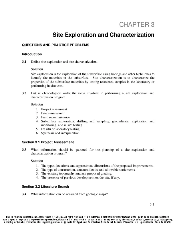
CHAPTER 3
Site Exploration and Characterization
QUESTIONS AND PRACTICE PROBLEMS
Introduction
3.1
Define site exploration and site characterization.
Solution
Site exploration is the exploration of the subsurface using borings and other techniques to
identify the materials in the subsurface. Site characterization is to characterize the
properties of the subsurface materials by testing recovered samples in the laboratory or
performing in situ tests.
3.2
List in chronological order the steps involved in performing a site exploration and
characterization program.
Solution
1. Project assessment
2. Literature search
3. Field reconnaissance
4. Subsurface exploration: drilling and sampling, groundwater exploration and
monitoring, and in situ testing
5. Ex situ or laboratory testing
6. Synthesis and interpretation
Section 3.1 Project Assessment
3.3
What information should be gathered for the planning of a site exploration and
characterization program?
Solution
1. The types, locations, and approximate dimensions of the proposed improvements.
2. The type of construction, structural loads, and allowable settlements.
3. The existing topography and any proposed grading.
4. The presence of previous development on the site, if any.
Section 3.2 Literature Search
3.4
What information can be obtained from geologic maps?
3-1
ยฉ 2011 Pearson Education, Inc., Upper Saddle River, NJ. All rights reserved. This publication is protected by Copyright and written permission should be obtained
from the publisher prior to any prohibited reproduction, storage in a retrieval system, or transmission in any form or by any means, electronic, mechanical, photocopying,
recording, or likewise. For information regarding permission(s), write to: Rights and Permissions Department, Pearson Education, Inc., Upper Saddle River, NJ 07458.
3-2
Site Exploration and Characterization
Chap. 3
Solution
Geologic maps show the extents of various geologic formations, alignments of faults,
major landslides, and other geologic features. They also may include cross-sections
showing subsurface conditions.
Section 3.5 Subsurface Exploration
3.5
Describe the following drilling methods and give advantages and disadvantages of each:
solid stem auger, hollow stem auger, rotary wash, and coring.
Solution
โข Solid stem auger: The auger is lowered into the hole and rotated to dig into the
soil. Then, it is removed, the soil is discharged onto the ground, and the process
is repeated. The hole is free of equipment between these cycles, which allows the
driller to insert sampling equipment at desired depths and obtain undisturbed
samples.
o Advantages: relatively cost effective; suitable for firm and dense soils or
soft rocks; allows samplers to obtain relatively undisturbed samples.
o Disadvantages: unsuitable for loose sands and gravels; ineffective below
the groundwater table; prone to squeezing and caving.
โข Hollow stem auger: Each auger section has a pipe core known as a stem, with a
temporary plug on the bottom of the first section. The driller screws these augers
into the ground, adding sections as needed. Unlike conventional augers, it is not
necessary to remove them to obtain samples. Instead, the driller removes the
temporary plug and inserts the sampler through the stem and into the soils below
the bottom auger section.
o Advantages: cost effective; suitable for all coarse- and fine-grained soils;
allows relatively undisturbed samples to be obtained through the hollow
stem; suitable below the groundwater table.
o Disadvantages: cost and size of the equipment required to operate the
auger.
โข Rotary wash: The boring is filled with drilling mud, a mixture of bentonite or
attapulgite clay and water. This drilling mud exerts a hydrostatic pressure on the
walls of the boring, thus preventing caving or squeezing. During drilling, the
cuttings are circulated to the ground surface by a pump. When sampling is
performed, the drilling tools are removed from the hole and the sampling tools are
lowered through the mud to the bottom, to retrieve relatively undisturbed samples.
o Advantages: cost effective; suitable for coarse-grained soils; allows
sampling of relatively undisturbed samples; suitable below the
groundwater table.
o Disadvantages: cost and size of the equipment required to operate the
system.
โข Coring: It consists of grinding away an annular zone with a rotary diamond drill
bit, leaving a cylindrical core which is captured by a core barrel and removed
from the ground, obtaining a nearly continuous undisturbed rock sample.
ยฉ 2011 Pearson Education, Inc., Upper Saddle River, NJ. All rights reserved. This publication is protected by Copyright and written permission should be obtained
from the publisher prior to any prohibited reproduction, storage in a retrieval system, or transmission in any form or by any means, electronic, mechanical, photocopying,
recording, or likewise. For information regarding permission(s), write to: Rights and Permissions Department, Pearson Education, Inc., Upper Saddle River, NJ 07458.
Chap. 3
Site Exploration and Characterization
3-3
o Advantages: suitable for rock sampling; allows a continuous sample to be
obtained.
o Disadvantages: cost and size of the equipment required to operate the
system; suitable only for rock sampling.
3.6
Describe the advantages and disadvantages of using an exploratory trench in site
exploration.
Solution
โข
โข
โข
โข
โข
Advantages
Provides more subsurface information than a boring of comparable depth.
Often is less expensive than a standard boring.
Disadvantages
Limited to shallow exploration.
Must be adequately shored or have trench side walls laid back to a sufficiently flat
slope before anyone enters.
Must be properly backfilled to avoid creating an artificial, soft zone.
Section 3.6 Soil and Rock Sampling
3.7
Describe the concept of sample disturbance and explain the relationship between sampler
type and disturbance.
Solution
Soil sample disturbance occurs when the soil is not recovered completely intact and its
in-place structure and stresses are modified in any way. Most disturbances occur in the
form of shearing and compression that occurs during the process of inserting the
sampling tool or sampler. During normal sampling, the relative amount of disturbance
can be quantified by the area ratio of the sampler, which is the ratio of the annular crosssectional area of the sampler tube to the circular cross-sectional area of the sampler itself.
For example, the heavy-wall sampler would create more sample disturbance than a
Shelby tube sampler due to its thicker wall.
3.8
Describe the Shelby tube sampler and the heavy-wall sampler and state the advantages
and disadvantages of each.
Solution
Shelby tube
โข
โข
โข
Advantages:
Provides soil samples.
Provides very good results in soft soils.
Provides minimal sample disturbance.
ยฉ 2011 Pearson Education, Inc., Upper Saddle River, NJ. All rights reserved. This publication is protected by Copyright and written permission should be obtained
from the publisher prior to any prohibited reproduction, storage in a retrieval system, or transmission in any form or by any means, electronic, mechanical, photocopying,
recording, or likewise. For information regarding permission(s), write to: Rights and Permissions Department, Pearson Education, Inc., Upper Saddle River, NJ 07458.
3-4
Site Exploration and Characterization
โข
โข
โข
Chap. 3
Disadvantages
Difficult to use in hard soils
The tube may bend or collapse due to the heavy loads required to drive through
dense soils.
It may become jammed into the ground and impossible to retrieve.
Heavy-wall Sampler
3.9
โข
โข
โข
Advantages:
Provides soil samples.
Provides sufficient strength under heavy loading.
Provide good results in medium dense and fine-grained soils.
โข
โข
Disadvantages
Provides a larger amount of sample disturbance due to its thickness.
Difficult to use in coarse soils.
A one-story, 50-m wide ร 90-m long manufacturing building is to be built on a site
underlain by medium dense to dense silty sand with occasional gravel. This soil probably
has better-than-average engineering properties and average uniformity. There are no
indications of previous grading or fill at this site, and the groundwater table is believed to
be about 30 m below the ground surface. We anticipate supporting this building on
spread footing foundations located about 0.5 m below the ground surface. There are no
accessibility problems at this site.
(a) How many exploratory borings will be required, and to what depths should they
be drilled?
(b) What type of drilling and sampling equipment would you recommend for this
project?
Solution
a.
A = (50 m )(90 m ) = 4500 m 2
Per Table 3.1 โ one boring per 200-400 m2 – โด Use 15 borings
Min Depth = 5S 0.7 + D = 5(1)
0.7
+ 0.5 = 5.5 m
Note: There is no single โcorrectโ answer to this problem. A range of answers
would be acceptable.
b. Some caving might occur in these soils, so a hollow stem auger would be a good
choice for this project. Alternatively, we might use a rotary wash rig or even a
conventional flight auger with casing as needed.
ยฉ 2011 Pearson Education, Inc., Upper Saddle River, NJ. All rights reserved. This publication is protected by Copyright and written permission should be obtained
from the publisher prior to any prohibited reproduction, storage in a retrieval system, or transmission in any form or by any means, electronic, mechanical, photocopying,
recording, or likewise. For information regarding permission(s), write to: Rights and Permissions Department, Pearson Education, Inc., Upper Saddle River, NJ 07458.
Chap. 3
Site Exploration and Characterization
3-5
3.10 A one-story, 20-m wide ร 50-m long concrete tilt-up office building is to be built at a site
near a wetlands. Previous exploratory borings at nearby sites encountered about 1 m of
moderately stiff clayey fill underlain by about 4 m of very soft organic silts and clays,
then 15 m of progressively stiffer sandy clays and clayey sands. Limestone bedrock is
located about 20 m below the ground surface. The groundwater table is thought to be at a
depth of about 0.5 m. Because of the soft soils, we will probably need to support this
building on deep foundations that extend at least into the stiffer soils, and possibly to
bedrock. There are no accessibility problems at this site.
(a) How many exploratory borings will be required, and to what depth should they be
drilled?
(b) What type of drilling and sampling equipment would you recommend for this
project, and what kinds of problems should the field crew be prepared to solve?
Solution
a.
A = (20 m )(50 m ) = 1000 m 2
Per Table 3.1 โ one boring per 100-300 m2 – โด Use 6 borings
Boring Plan
3 Borings to 18 m depth
3 boring 2 m into bedrock (approx. 22 m depth)
Note: There is no single โcorrectโ answer to this problem. A range of answers
would be acceptable.
b. The very soft organic silts and clays will almost certainly have squeezing and caving
problems. In addition, some of the borings need to penetrate into the limestone bedrock.
The drilling method will need to be selected to accommodate both of these requirements.
For this project we would probably use a rotary wash rig, which can drill through the soil
without caving problems, then add rotary rock drilling bits when reaching the limestone.
Other kinds of drilling equipment also could be used.
Shelby tube samples would be obtained in the soil strata. It may be possible to use
a heavy-wall sampler in the limestone.
The field crew should be prepared to encounter caving, difficulties in sampling,
and possible difficulties in drilling through the limestone.
3.11 A ten-story steel-frame office building with a 200 ft ร 200 ft footprint is to be built on a
site underlain by alluvial sands and silts. These soils are fairly uniform and probably
have good engineering properties. The building will have one 12-ft deep basement and
will probably be supported on either a mat foundation located 5 ft below the bottom of
ยฉ 2011 Pearson Education, Inc., Upper Saddle River, NJ. All rights reserved. This publication is protected by Copyright and written permission should be obtained
from the publisher prior to any prohibited reproduction, storage in a retrieval system, or transmission in any form or by any means, electronic, mechanical, photocopying,
recording, or likewise. For information regarding permission(s), write to: Rights and Permissions Department, Pearson Education, Inc., Upper Saddle River, NJ 07458.
3-6
Site Exploration and Characterization
Chap. 3
the basement, or a deep foundation extending about 60 ft below the bottom of the
basement. The groundwater table is about 30 ft below the ground surface and bedrock is
several 100 ft below the ground surface. There are no accessibility problems at this site.
(a) How many exploratory borings will be required, and to what depth should they be
drilled?
(b) What type of drilling and sampling equipment would you recommend for this
project?
Solution
a.
A = (200 ft )(200 ft ) = 40,000 m 2
Per Table 3.1 โ one boring per 3,000 โ 10,000 ft2 โ โด Use 8 borings
Min depth = 10 S 0.7 + D = 10(10 )
0.7
+ 17 = 67 ft
Since deep foundations are a possibility, at least some of the borings should
extend below the toe of these piles, which are estimated to be 12 + 60 = 72 ft below the
ground surface. This produces a boring depth of about 90 ft.
Boring Plan
5 borings to 70 ft depth
3 borings to 90 ft depth
Note: There is no single โcorrectโ answer to this problem. A range of answers
would be acceptable.
b. Alluvial sand and silt below the groundwater table might experience some caving. We
probably would use a hollow stem auger for this project. Alternatively, we might use a
rotary wash rig.
3.12 A small commercial development consisting of a one-story supermarket and a one-story
retail store building is to be built on the site shown in Figure 3.40. The proposed spread
footing foundations will be located at a depth of 2 ft below the ground surface. The site
has never been developed before, but a study of old aerial photographs indicates a fill was
placed in the northeast section. This fill appears to be up to 5-ft thick, probably was not
compacted, and most likely will need to be removed during construction. However, we
may be able to reuse this material as fill, so long as it does not contain trash or other
deleterious substances. The remainder of the soils are probably stiff clayey silts and
sandy silts. The groundwater table is believed to be about 20 ft below the ground surface.
There are no accessibility problems at this site.
ยฉ 2011 Pearson Education, Inc., Upper Saddle River, NJ. All rights reserved. This publication is protected by Copyright and written permission should be obtained
from the publisher prior to any prohibited reproduction, storage in a retrieval system, or transmission in any form or by any means, electronic, mechanical, photocopying,
recording, or likewise. For information regarding permission(s), write to: Rights and Permissions Department, Pearson Education, Inc., Upper Saddle River, NJ 07458.
Chap. 3
Site Exploration and Characterization
3-7
Develop a subsurface exploration program and present it as a 250โ350 word
memo to your field crew instructing them what to do. Be sure to include a copy of the
site plan marked with the proposed location of each activity.
Solution
Market
A = (200 ft )(150 ft ) = 30,000 ft 2
Per Table 3.1 โ one boring per 2000 โ 4000 ft2 โ โด Use 10 borings
Min depth = 15S 0.7 + D = 15(1)
0.7
+ 2 = 17 ft
Retail stores
A = (50 ft )(235 ft ) = 12,000 ft 2
ยฉ 2011 Pearson Education, Inc., Upper Saddle River, NJ. All rights reserved. This publication is protected by Copyright and written permission should be obtained
from the publisher prior to any prohibited reproduction, storage in a retrieval system, or transmission in any form or by any means, electronic, mechanical, photocopying,
recording, or likewise. For information regarding permission(s), write to: Rights and Permissions Department, Pearson Education, Inc., Upper Saddle River, NJ 07458.
3-8
Site Exploration and Characterization
Chap. 3
Per Table 3.1 โ one boring per 2000 โ 4000 ft2 โ โด Use 4 borings
Min depth = 15S 0.7 + D = 15(1)
0.7
+ 2 = 17 ft
Commentary: The site exploration and characterization program needs to determine depth
and lateral extent of the old fill. Since its maximum depth is probably about 5 ft, it would
be best to explore it using backhoe trenches instead of borings. However, the evaluation
of the natural soils for foundation design purposes is best done using borings. The
locations of these trenches and borings should be shown on the plan view of the site.
Memorandum to Field Crew
Please schedule a backhoe and a hollow stem drill rig to trench and drill at the
proposed shopping center site. The approximate locations and depths of these trenches
and borings are shown on the attached drawing.
An old fill is located in the northeast corner of the site, as shown on the map. The
lateral limits shown are approximate, and the depth is probably no more than 5 ft. The
backhoe trenches need to penetrate through this fill, so we will know its exact depth. We
also need to determine if any trash or other unsuitable materials are present to help us
decide if the soils in the fill can be reused or if they need to be hauled away. Please obtain
a few representative bulk samples of the old fill.
The borings are for foundation design purposes. I expect the natural soils will be
primarily stiff clayey silts and sandy silts. Please use a heavy-wall sampler to obtain
undisturbed samples of each stratum, with sampling intervals no greater than 5 ft.
Finally please obtain a few representative samples of the surface soils in the
parking lot area.
Note: There is no single โcorrectโ answer to this problem. A range of answers
would be acceptable. No drawing showing the trenching and boring locations is provided
here.
Section 3.7 Groundwater Exploration and Monitoring
3.13 Describe how to install an observation well and what it measures.
Solution
The installation of an observation well consists of drilling a borehole, inserting a slotted
plastic pipe, and backfilling around the pipe with pervious soils and sealing the top of the
backfill with an impervious cap. The slotted pipe allows water to flow freely into or out
of this pipe, so the water level inside is the groundwater table. An observation well gives
the depth to the groundwater table that can be measured, for example, with an electronic
probe.
ยฉ 2011 Pearson Education, Inc., Upper Saddle River, NJ. All rights reserved. This publication is protected by Copyright and written permission should be obtained
from the publisher prior to any prohibited reproduction, storage in a retrieval system, or transmission in any form or by any means, electronic, mechanical, photocopying,
recording, or likewise. For information regarding permission(s), write to: Rights and Permissions Department, Pearson Education, Inc., Upper Saddle River, NJ 07458.
Chap. 3
Site Exploration and Characterization
3-9
Section 3.9 In Situ Testing
3.14 The vertical effective stress at Sample 1 in Figure 3.14 is 405 lb/ft2. Compute N1 ,60.
Solution
N1,60 = N 60
2000 lb/ft 2
2000 lb/ft 2
= 10
= 22
405 lb/ft 2
ฯz’
3.15 The vertical effective stress at Sample 3 in Figure 3.14 is 1270 lb/ft2. Compute N1 ,60.
Solution
N1, 60 = N 60
2000 lb/ft 2
2000 lb/ft 2
= 42
= 52
1270 lb/ft 2
ฯz’
3.16 A standard penetration test has been performed at a depth of 6.5 m in a medium sand
using a standard sampler and a USA-style donut hammer. The N-value recorded in the
field was 16. The boring diameter was about 100 mm, and the vertical effective stress at
the test location was 85 kPa. Compute N1 ,60.
Solution
N 60 =
E m C B C S C R N (0.45)(1.00)(1.00)(0.95)(16)
=
= 11.4
0.60
0.60
N1,60 = N 60
100 kPa
100 kPa
= 11.4
= 12
85 kPa
ฯz’
3.17 Using Figure 3.29, classify the soils between depths of 23 and 48 ft in the CPT results
presented in Figure 3.28. Why are there spikes in the qc, fsc, and Rf curves between these
depths?
Solution
Per figure 3.28, most of the soil between 23 and 48 ft has the following characteristics:
qc = 17 tsf = 17 kg/cm
Rf = 2.6%.
Per Figure 3.29, The soil is a clayey silt or silty clay, the spikes indicate a higher
amounts of sand content.
3.18 Using Figure 3.29, classify the soils between depths of 66 and 80 ft in the CPT results
presented in Figure 3.29. Why are there spikes in the qc, fsc, and Rf curves between
depths of 76 and 78 ft?
ยฉ 2011 Pearson Education, Inc., Upper Saddle River, NJ. All rights reserved. This publication is protected by Copyright and written permission should be obtained
from the publisher prior to any prohibited reproduction, storage in a retrieval system, or transmission in any form or by any means, electronic, mechanical, photocopying,
recording, or likewise. For information regarding permission(s), write to: Rights and Permissions Department, Pearson Education, Inc., Upper Saddle River, NJ 07458.
3-10
Site Exploration and Characterization
Chap. 3
Solution
Per figure 3.29, most of the soil between 66 and 80 ft has the following characteristics:
qc = 17 tsf = 17 kg/cm2
Rf = 2.6%
Per Figure 3.30, the soil is a clayey silt or silty clay, the spikes between 76 and 78
ft indicate a sand seam.
3.19 A cone penetration test on a sandy soil with mean particle size of 0.5 mm produced a qc
of 80 kg/cm2. Estimate the equivalent SPT N60-value.
Solution
Per Figure 3.32 โ qc/N60 = 4.5 (Kulhawy & Manye, 1990):
N 60 =
80
= 18
4 .5
3.20 Compare the standard penetration test and the Becker penetration test.
Solution
The Standard Penetration Test (SPT) is used mostly for medium dense and fine-grained
soils. The Becker penetration test is used for very dense and coarse soils. For both, the
hammer blow-count is monitored to advance the casing 1 ft, recorded, and used for
correlation with in situ soil properties. But the major difference is the ability of the SPT
sampler to retrieve a relatively undisturbed sample for the purpose of soil classification.
3.21 Describe how to perform a pressuremeter test and what it measures.
Solution
The pressuremeter test (PMT) produces direct measurements of soil compressibility and
lateral stresses. The test entails placement of a cylindrical balloon that is inserted into a
carefully drilled boring in the ground and inflated. The PMT measures the volume of the
void produced by the balloon and pressure applied to the surrounding soil. These
measurements can be used to evaluate the in situ stress, the compressibility and strength
of the adjacent soil.
3.22 Describe how to perform a dilatometer test and what it measures.
Solution
The dilatometer test (DMT) entails measuring the pressure applied by the surrounding
soil at three different moments. The primary benefit of the DMT is that it measures the
lateral stress condition and compressibility of the soil. The dilatometer is embedded into
the soil and pressurized by nitrogen gas. The โA pressureโ is recorded when the center of
the membrane has moved 0.05 mm into the soil. The โB pressureโ is recorded when the
ยฉ 2011 Pearson Education, Inc., Upper Saddle River, NJ. All rights reserved. This publication is protected by Copyright and written permission should be obtained
from the publisher prior to any prohibited reproduction, storage in a retrieval system, or transmission in any form or by any means, electronic, mechanical, photocopying,
recording, or likewise. For information regarding permission(s), write to: Rights and Permissions Department, Pearson Education, Inc., Upper Saddle River, NJ 07458.
Chap. 3
Site Exploration and Characterization
3-11
center of the membrane has moved 1.10 mm into the soil. The โC pressureโ is recorded
when the once the membrane has returned to its original position once deflated. Once
these values are determined and corrected using equipment calibration factors, they are
expressed as the DMT indices.
Comprehensive
3.23 An engineer is planning to use a 24-inch diameter bucket auger similar to the one in
Figure 3.7 to drill several exploratory borings at a site adjacent to a lake. The underlying
soils are probably soft clays and silts with N-values of less than 5. Is this a wise choice?
Why or why not?
Solution
This would be very poor choice, and is almost certainly doomed to failure. Soft clays and
silts are prone to caving and squeezing, especially in such a large diameter boring. It
would be much better to use a rotary wash rig or a hollow stem rig.
3.24 What type of soil sampling equipment would be most appropriate for the soils described
in Problem 3.23? Why?
Solution
Shelby tube samples would be ideal in these soils because they are so soft. This type of
sampler induces much less disturbance than heavy-wall samplers.
3.25 A large compacted fill is to be placed on a site underlain by a 15 m thick layer of
saturated clay. The weight of this fill will cause the clay layer to consolidate, which will
result in large settlements at the ground surface. Since these settlements would have an
adverse effect on buildings and other improvements planned for this site, a settlement rate
analysis, similar to those we will discuss in Chapter 11, is to be performed to estimate the
time required for a certain percentage of the settlement to be completed.
A series of exploratory borings have already been drilled at this site, samples have
been recovered, and laboratory tests have been performed to evaluate the consolidation
properties of the clay. However, to complete the settlement rate analysis, we need to
know if thin horizontal sand seams are present in the clay, and the approximate spacing
between these seams. If they exist at all, these seams are probably less than 100 mm
thick. Although some of the undisturbed samples contained sand seams, more
information is needed.
What kind of additional exploration would you do to determine whether or not
more sand seams are present? Be sure to consider both technical feasibility and cost, and
explain the reason for your choice.
Solution
One method would be to perform a series of cone penetration tests. Sand seams would
have a greater qc, and a lower Rf than the surrounding clay, and thus would show up as
ยฉ 2011 Pearson Education, Inc., Upper Saddle River, NJ. All rights reserved. This publication is protected by Copyright and written permission should be obtained
from the publisher prior to any prohibited reproduction, storage in a retrieval system, or transmission in any form or by any means, electronic, mechanical, photocopying,
recording, or likewise. For information regarding permission(s), write to: Rights and Permissions Department, Pearson Education, Inc., Upper Saddle River, NJ 07458.
3-12
Site Exploration and Characterization
Chap. 3
โspikesโ on the test results. Seams 100 mm thick would most likely show up in the test
results, but very thin seams might not.
An alternative method would be to take nearly โcontinuousโ Shelby tube samples
in a boring. This involves taking a Shelby tube sample, drilling the boring to the depth
where the bottom of the sampler was, then taking another sample. Thus, the top of the
second sample is, in theory, at the same depth as the bottom of the first sample. This
process continues with additional samples as necessary. The Shelby tube samples would
then be extracted in the laboratory and examined. This method would be much more
expensive than performing CPTs, but we would be nearly assured of finding sandy seams
if they truly exist at the boring location.
3.26 A level building pad is to be built at the site shown in Figure 3.41 by cutting and filling as
shown. The final pad elevation is to be 215 ft. Then, a three-story steel-frame office
building is to be built.
Five exploratory borings have been drilled to determine the subsurface conditions.
The logs from these borings were summarized as follows:
Boring 1
Groundwater table depth = 44 ft
Depth (ft)
Soil or Rock Conditions
0 – 18
Sandy clay
18 – 35
Clayey sand
35 – 52
Silty sand
52 – 55
Sandstone bedrock
Boring 2
Groundwater table depth = 31 ft
Depth (ft)
Soil or Rock Conditions
0 – 28
Clayey sand
28 – 36
Silty sand
36 – 39
Sandstone bedrock
Boring 3
Groundwater table depth = 41 ft
Depth (ft)
Soil or Rock Conditions
0 – 34
Clayey sand
34 – 48
Silty sand
48 – 52
Sandstone bedrock
ยฉ 2011 Pearson Education, Inc., Upper Saddle River, NJ. All rights reserved. This publication is protected by Copyright and written permission should be obtained
from the publisher prior to any prohibited reproduction, storage in a retrieval system, or transmission in any form or by any means, electronic, mechanical, photocopying,
recording, or likewise. For information regarding permission(s), write to: Rights and Permissions Department, Pearson Education, Inc., Upper Saddle River, NJ 07458.
Chap. 3
Site Exploration and Characterization
3-13
Boring 4
Groundwater table depth = 40 ft
Depth (ft)
Soil or Rock Conditions
0 – 33
Clayey sand
33 – 45
Silty sand
45 – 47
Sandstone bedrock
Boring 5
Groundwater table depth = 49 ft
Depth (ft)
Soil or Rock Conditions
0 – 17
Clayey sand
17 – 25
Silt
25 – 42
Clayey sand
42 – 57
Silty sand
57 – 60
Sandstone bedrock
Develop cross-sections A-Aโฒ and B-Bโฒ and show the soil profiles beneath the
proposed building. The profiles should be similar to the one in Figure 3.36 and should
include the existing and proposed grades, the proposed building, strata boundaries, and
the groundwater table. Do not use an exaggerated vertical scale.
ยฉ 2011 Pearson Education, Inc., Upper Saddle River, NJ. All rights reserved. This publication is protected by Copyright and written permission should be obtained
from the publisher prior to any prohibited reproduction, storage in a retrieval system, or transmission in any form or by any means, electronic, mechanical, photocopying,
recording, or likewise. For information regarding permission(s), write to: Rights and Permissions Department, Pearson Education, Inc., Upper Saddle River, NJ 07458.
3-14
Site Exploration and Characterization
Chap. 3
Solution
ยฉ 2011 Pearson Education, Inc., Upper Saddle River, NJ. All rights reserved. This publication is protected by Copyright and written permission should be obtained
from the publisher prior to any prohibited reproduction, storage in a retrieval system, or transmission in any form or by any means, electronic, mechanical, photocopying,
recording, or likewise. For information regarding permission(s), write to: Rights and Permissions Department, Pearson Education, Inc., Upper Saddle River, NJ 07458.
Document Preview (14 of 323 Pages)
User generated content is uploaded by users for the purposes of learning and should be used following SchloarOn's honor code & terms of service.
You are viewing preview pages of the document. Purchase to get full access instantly.
-37%
Solution Manual For Geotechnical Engineering: Principles and Practices, 2nd Edition
$18.99 $29.99Save:$11.00(37%)
24/7 Live Chat
Instant Download
100% Confidential
Store
William Taylor
0 (0 Reviews)
Best Selling
Solution Manual for Designing the User Interface: Strategies for Effective Human-Computer Interaction, 6th Edition
$18.99 $29.99Save:$11.00(37%)
Chemistry: Principles And Reactions, 7th Edition Test Bank
$18.99 $29.99Save:$11.00(37%)
2023-2024 ATI Pediatrics Proctored Exam with Answers (139 Solved Questions)
$18.99 $29.99Save:$11.00(37%)
Data Structures and Other Objects Using C++ 4th Edition Solution Manual
$18.99 $29.99Save:$11.00(37%)
Test Bank for Strategies For Reading Assessment And Instruction: Helping Every Child Succeed, 6th Edition
$18.99 $29.99Save:$11.00(37%)
Test Bank for Hospitality Facilities Management and Design, 4th Edition
$18.99 $29.99Save:$11.00(37%)