Solution Manual for Electrical Wiring: Industrial, Fifth Canadian Edition

Preview Extract
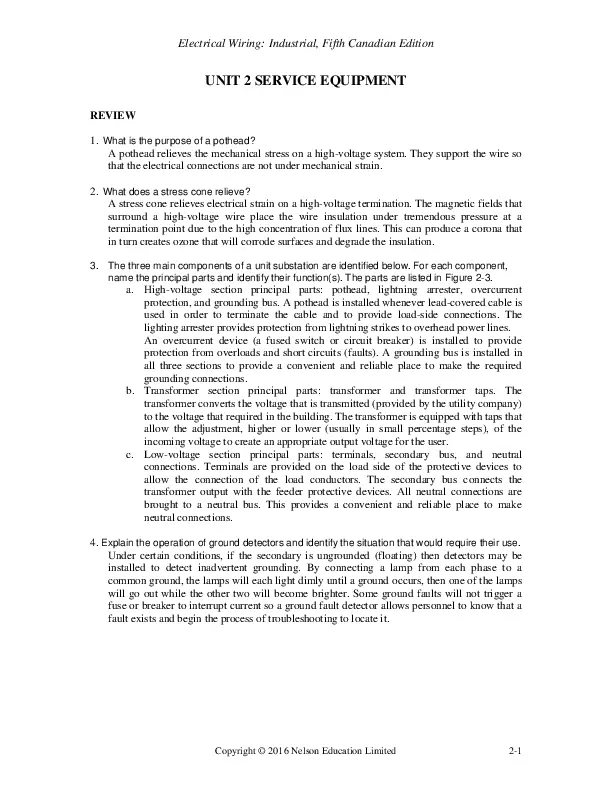
Electrical Wiring: Industrial, Fifth Canadian Edition UNIT 2 SERVICE EQUIPMENT REVIEW 1. What is the purpose of a pothead? A pothead relieves the mechanical stress on a high-voltage system. They support the wire so that the electrical connections are not under mechanical strain. 2. What does a stress cone relieve? A stress cone relieves electrical strain on a high-voltage termination. The magnetic fields that surround a high-voltage wire place the wire insulation under tremendous pressure at a termination point due to the high concentration of flux lines. This can produce a corona that in turn creates ozone that will corrode surfaces and degrade the insulation. 3. The three main components of a unit substation are identified below. For each component, name the principal parts and identify their function(s). The parts are listed in Figure 2-3. a. High-voltage section principal parts: pothead, lightning arrester, overcurrent protection, and grounding bus. A pothead is installed whenever lead-covered cable is used in order to terminate the cable and to provide load-side connections. The lighting arrester provides protection from lightning strikes to overhead power lines. An overcurrent device (a fused switch or circuit breaker) is installed to provide protection from overloads and short circuits (faults). A grounding bus is installed in all three sections to provide a convenient and reliable place to make the required grounding connections. b. Transformer section principal parts: transformer and transformer taps. The transformer converts the voltage that is transmitted (provided by the utility company) to the voltage that required in the building. The transformer is equipped with taps that allow the adjustment, higher or lower (usually in small percentage steps), of the incoming voltage to create an appropriate output voltage for the user. c. Low-voltage section principal parts: terminals, secondary bus, and neutral connections. Terminals are provided on the load side of the protective devices to allow the connection of the load conductors. The secondary bus connects the transformer output with the feeder protective devices. All neutral connections are brought to a neutral bus. This provides a convenient and reliable place to make neutral connections. 4. Explain the operation of ground detectors and identify the situation that would require their use. Under certain conditions, if the secondary is ungrounded (floating) then detectors may be installed to detect inadvertent grounding. By connecting a lamp from each phase to a common ground, the lamps will each light dimly until a ground occurs, then one of the lamps will go out while the other two will become brighter. Some ground faults will not trigger a fuse or breaker to interrupt current so a ground fault detector allows personnel to know that a fault exists and begin the process of troubleshooting to locate it. Copyright ยฉ 2016 Nelson Education Limited 2-1 Electrical Wiring: Industrial, Fifth Canadian Edition 5. Describe a station ground electrode. A station ground consists of four 19 mm ร— 3 m ground rods spaced at least 3 m apart. The rods are interconnected with 2/0 bare copper cable buried between 150 mm below finished grade and 600 mm below station grade. 6. List the procedures to be followed when entering a confined space. These are the procedures to be followed when entering a confined space: ๏‚ท Obtain a confined space entry permit. ๏‚ท Read and observe the entry permit requirements. ๏‚ท Obtain and use protective equipment required by the permit. ๏‚ท Test the atmosphere before entering the space. ๏‚ท Monitor the atmosphere during the entry. ๏‚ท Have an attendant stationed outside the workspace. ๏‚ท Stay alert to hazards that may be found in a confined space. ๏‚ท Immediately exit the confined space if ordered to do so by the attendant; an automatic alarm sounds; you notice signs of dizziness, blurred vision, or shortness of breath in you or in others; or you feel you are in danger. 7. Calculate the pulling tension on a run of conduit containing three conductors that weigh 3 kg per metre each. The run consists of a straight section 25 m long, a 90ยฐ bend, and a second straight section 40 m long. The pulling tension throughout the run would be as follows: Pulling tension: at start of run at end of 25 m straight length at end of bend at end of second straight piece Ts = 0 TS1 = L ร— W ร— f = 25 m ร— 9 kg ร— 0.5 = 112.5 kg TB1 = TS1 ร— bending coefficient = 112.5 kg ร— 2.2 = 247.5 kg TS2 = TB1 + (L ร— W ร— f) = 247.5 + (40 ร— 9 ร— 0.5) = 427.5 kg 8. What maximum size overcurrent device would be required in the primary disconnect of a 600 V primary and to a 120/208 V secondary, three-phase, four-wire, 45 kVA drytype transformer? CEC Rule 26-256 Iprimary = kVA/โˆš3 * Vprimary * 125% = 54.1265 A fuse. CEC Rule 26-256 (3) allows you to go to a 60 A fuse. That would allow you to get the full 45 kVA out of the transformer. CEC Rule 26-256 (1) would limit you to a 50 A (43.3 * 1.25) fuse since the rated primary current of the transformer is 43.3 A. This would result in less available current on the secondary due to the transformer, so it is common to quote CEC Rule 26-256 (3) and take full advantage of the transformer. Either answer is technically correct but common trade practice would be to use a 60 A fuse. 2-2 Copyright ยฉ 2016 by Nelson Education Ltd.

Document Preview (2 of 103 Pages)

User generated content is uploaded by users for the purposes of learning and should be used following SchloarOn's honor code & terms of service.
You are viewing preview pages of the document. Purchase to get full access instantly.

Shop by Category See All


Shopping Cart (0)

Your bag is empty

Don't miss out on great deals! Start shopping or Sign in to view products added.

Shop What's New Sign in