Solution Manual For Fundamentals of Heat and Mass Transfer, 8th Edition

Preview Extract
PROBLEM 2.1 KNOWN: Axisymmetric object with varying cross-sectional area and different temperatures at its two ends, insulated on its sides. FIND: Shapes of heat flux distribution and temperature distribution. SCHEMATIC: T1 T2 T1 > T2 dx x L ASSUMPTIONS: (1) Steady-state, (2) One-dimensional conduction, (3) Constant properties, (4) Adiabatic sides, (5) No internal heat generation. (6) Surface temperatures T 1 and T 2 are fixed. ANALYSIS: For the prescribed conditions, it follows from conservation of energy, Eq. 1.12c, ๏€ฆ in = E๏€ฆ out or q x = q x+dx . Hence that for a differential control volume, E q x is independent of x. Therefore โ€ฒโ€ฒx A c constant = q x q= (1) where A c is the cross-sectional area perpendicular to the x-direction. Therefore the heat flux must be inversely proportional to the cross-sectional area. The radius of the object first increases and then decreases linearly with x, so the cross-sectional area increases and then decreases as x2. < The resulting heat flux distribution is sketched below. q" 0 0 x L < Continuedโ€ฆ PROBLEM 2.1 (Cont.) To find the temperature distribution, we can use Fourierโ€™s law: qโ€ฒโ€ฒx = โˆ’k dT dx (2) Therefore the temperature gradient is negative and its magnitude is proportional to the heat flux. The temperature decreases most rapidly where the heat flux is largest and more slowly where the heat flux is smaller. Based on the heat flux plot above we can prepare the sketch of the temperature distribution below. T 0 0 x L < The temperature distribution is independent of the thermal conductivity. The heat rate and local heat fluxes are both proportional to the thermal conductivity of the material. < COMMENTS: If the heat rate was fixed the temperature difference, T 1 – T 2 , would be inversely proportional to the thermal conductivity. The temperature distribution would be of the same shape, but local temperatures T(x) would vary as the thermal conductivity is adjusted. PROBLEM 2.2 KNOWN: Hot water pipe covered with thick layer of insulation. FIND: Sketch temperature distribution and give brief explanation to justify shape. SCHEMATIC: ASSUMPTIONS: (1) Steady-state conditions, (2) One-dimensional (radial) conduction, (3) No internal heat generation, (4) Insulation has uniform properties independent of temperature and position. ANALYSIS: Fourierโ€™s law, Eq. 2.1, for this one-dimensional (cylindrical) radial system has the form dT dT qr = โˆ’kA r = โˆ’k ( 2ฯ€ r๏ฌ ) dr dr where A r = 2ฯ€r๏ฌ and ๏ฌ is the axial length of the pipe-insulation system. Recognize that for steadystate conditions with no internal heat generation, an energy balance on the system requires E๏€ฆ in = E๏€ฆ out since E๏€ฆ g = E๏€ฆ st = 0. Hence q r = Constant. That is, q r is independent of radius (r). Since the thermal conductivity is also constant, it follows that ๏ฃฎ dT ๏ฃน r ๏ฃฏ ๏ฃบ = Constant. ๏ฃฐ dr ๏ฃป This relation requires that the product of the radial temperature gradient, dT/dr, and the radius, r, remains constant throughout the insulation. For our situation, the temperature distribution must appear as shown in the sketch. < COMMENTS: (1) Note that, while q r is a constant and independent of r, q โ€ฒโ€ฒr is not a constant. How bg does q โ€ฒโ€ฒr r vary with r? (2) Recognize that the radial temperature gradient, dT/dr, decreases with increasing radius. PROBLEM 2.3 KNOWN: A spherical shell with prescribed geometry and surface temperatures. FIND: Sketch temperature distribution and explain shape of the curve. SCHEMATIC: ASSUMPTIONS: (1) Steady-state conditions, (2) One-dimensional conduction in radial (spherical coordinates) direction, (3) No internal generation, (4) Constant properties. ANALYSIS: Fourierโ€™s law, Eq. 2.1, for this one-dimensional, radial (spherical coordinate) system has the form ( ) dT dT qr = โˆ’k A r = โˆ’k 4ฯ€ r 2 dr dr where A r is the surface area of a sphere. For steady-state conditions, an energy balance on the system ๏€ฆ in = E๏€ฆ out , since E๏€ฆ g = E๏€ฆ st = 0. Hence, yields E qin = q out = qr โ‰  qr ( r ). That is, q r is a constant, independent of the radial coordinate. Since the thermal conductivity is constant, it follows that ๏ฃฎ dT ๏ฃน r 2 ๏ฃฏ ๏ฃบ = Constant. ๏ฃฐ dr ๏ฃป This relation requires that the product of the radial temperature gradient, dT/dr, and the radius 2 squared, r , remains constant throughout the shell. Hence, the temperature distribution appears as shown in the sketch. 0 ๏ฃด where ๏ฃฒ ๏ฃฎ dT ๏ฃน 2 ๏ฃด ๏ฃฏ๏ฃฐ dx ๏ฃบ๏ฃป > 0 ๏ฃณ from which it follows that for a > 0: d 2 T / dx 2 < 0 a = 0: d 2 T / dx 2 = 0 a 0. 0: k decreases with increasing x = > | dT/dx | increases with increasing x a = 0: k = k o = > dT/dx is constant a | dT/dx | decreases with increasing x. PROBLEM 2.5 KNOWN: Irradiation and absorptivity of aluminum, glass and aerogel. FIND: Ability of the protective barrier to withstand the irradiation in terms of the temperature gradients that develop in response to the irradiation. SCHEMATIC: G = 10 x 106 W/m2 ฮฑ al = 0.2 x ฮฑ gl = 0.9 ฮฑ a = 0.8 ASSUMPTIONS: (1) One-dimensional conduction in the x-direction, (2) Constant properties, (c) Negligible emission and convection from the exposed surface. PROPERTIES: Table A.1, pure aluminum (300 K): k al = 238 W/mโ‹…K. Table A.3, glass (300 K): k gl = 1.4 W/mโ‹…K. ANALYSIS: From Eqs. 1.6 and 2.32 -k โˆ‚T = qโ€ฒโ€ฒs = G abs = ฮฑG โˆ‚x x=0 or โˆ‚T ฮฑG =โˆ‚x x=0 k The temperature gradients at x = 0 for the three materials are: Material aluminum glass aerogel < โˆ‚T / โˆ‚x x=0 (K/m) 8.4 x 10³ 6.4 x 10⁶ 1.6 x 10⁹ COMMENT: It is unlikely that the aerogel barrier can sustain the thermal stresses associated with the large temperature gradient. Low thermal conductivity solids are prone to large temperature gradients, and are often brittle. PROBLEM 2.6 KNOWN: One-dimensional system with prescribed thermal conductivity and thickness. FIND: Unknowns for various temperature conditions and sketch distribution. SCHEMATIC: L = 0.35 m T1 dT , Temperature gradient dx k = 50 W/mโˆ™K T2 qxโ€œ x ASSUMPTIONS: (1) Steady-state conditions, (2) One-dimensional conduction, (3) No internal heat generation, (4) Constant properties. ANALYSIS: The rate equation and temperature gradient for this system are dT dT T2 โˆ’ T1 qโ€ฒโ€ฒx = โˆ’k and = . dx dx L Using Eqs. (1) and (2), the unknown quantities for each case can be determined. (a) dT dx = ( โˆ’20 โˆ’ 50 ) K = โˆ’200 K/m < 0.35m W K๏ฃน ๏ฃฎ qโ€ฒโ€ฒx =โˆ’50 ร— โˆ’200 =10.0 kW/m 2 . ๏ฃฏ ๏ฃบ mโ‹…K ๏ฃฐ m๏ฃป (1,2) 50ยฐC qxโ€œ < -20ยฐC < x dT (b) = dx โˆ’10 โˆ’ ( โˆ’30 ) ) K (= 57 K/m 0.35m W ๏ฃฎ K๏ฃน = qโ€ฒโ€ฒx = โˆ’50 ร— 57 โˆ’2.86 kW/m 2 . ๏ฃฏ ๏ฃบ mโ‹…K ๏ฃฐ m๏ฃป < qxโ€œ -10ยฐC < < -30ยฐC x (c) W K๏ฃน ๏ฃฎ โˆ’50 ร— ๏ฃฏ160 ๏ฃบ = โˆ’8.0 kW/m 2 qโ€ฒโ€ฒx = mโ‹…K ๏ฃฐ m๏ฃป T2 =L โ‹… dT dx ๏ฃฎ ๏ฃฏ๏ฃฐ + T1 =0.35m ร— 160 T2 = 126๏ฏ C. K๏ฃน < qxโ€œ ๏ฏ dT = 160 K/m dx + 70 C. m ๏ฃบ๏ฃป < 70ยฐC < x Continued โ€ฆ PROBLEM 2.6 (Cont.) (d) qโ€ฒโ€ฒx =โˆ’50 ๏ฃฎ mโ‹…K ๏ฃฐ W T1 = T2 โˆ’ L โ‹… (e) ร— ๏ฃฏ โˆ’80 dT dx K๏ฃน 2 ๏ฃบ =4.0 kW/m m๏ฃป ๏ฃฎ ๏ฃฏ๏ฃฐ = 40๏ฏ C โˆ’ 0.35m โˆ’80 qxโ€œ < dT = -80 K/m dx K๏ฃน m ๏ฃบ๏ฃป 40ยฐC T1 = 68๏ฏ C. < W K๏ฃน ๏ฃฎ qโ€ฒโ€ฒx = โˆ’50 ร— ๏ฃฏ 200 ๏ฃบ = โˆ’10.0 kW/m 2 mโ‹…K ๏ฃฐ m๏ฃป < x 30ยฐC qxโ€œ dT = 200 K/m dx K๏ฃน ๏ฃฎ =30 C โˆ’ 0.35m 200 =โˆ’40๏ฏ C. < T1 =T2 โˆ’ L โ‹… ๏ฃฏ ๏ฃบ dx m ๏ฃฐ ๏ฃป dT < ๏ฏ x < PROBLEM 2.7 KNOWN: Plane wall with prescribed thermal conductivity, thickness, and surface temperatures. FIND: Heat flux, q โ€ฒโ€ฒx , and temperature gradient, dT/dx, for the three different coordinate systems shown. SCHEMATIC: T1 = 500 K T2 = 700 K k = 120 W/mโˆ™K L = 120 mm ASSUMPTIONS: (1) One-dimensional heat flow, (2) Steady-state conditions, (3) No internal generation, (4) Constant properties. ANALYSIS: The rate equation for conduction heat transfer is q โ€ฒโ€ฒx = โˆ’ k dT , dx (1) where the temperature gradient is constant throughout the wall and of the form dT T ( L ) โˆ’ T ( 0 ) = . dx L (2) Substituting numerical values, find the temperature gradients, dT T2 โˆ’ T1 (a) = = dx L (b) ( 700 โˆ’ 500 )K = 1667 K/m 0.120m dT T1 โˆ’ T2 ( 500 โˆ’ 700 ) K = = = โˆ’1667 K/m dx L 0.120m dT T2 โˆ’ T1 (c) = = dx L ( 700 โˆ’ 500 )K = 1667 K/m. 0.120m < < < The heat rates, using Eq. (1) with k = 120 W/mโ‹…K, are (a) W qโ€ฒโ€ฒx = -120 ร— 1667 K/m=-200 kW/m2 mโ‹…K < (b) W qโ€ฒโ€ฒx = โˆ’120 ( โˆ’1667 K/m)=+200 kW/m2 mโ‹…K < (c) qโ€ฒโ€ฒx = -120 W (1667 K/m)=-200 kW/m2 mโ‹…K < PROBLEM 2.8 KNOWN: Two-dimensional body with specified thermal conductivity and two isothermal surfaces of prescribed temperatures; one surface, A, has a prescribed temperature gradient. FIND: Temperature gradients, โˆ‚T/โˆ‚x and โˆ‚T/โˆ‚y, at the surface B. SCHEMATIC: ASSUMPTIONS: (1) Two-dimensional conduction, (2) Steady-state conditions, (3) No heat generation, (4) Constant properties. ANALYSIS: At the surface A, the temperature gradient in the x-direction must be zero. That is, (โˆ‚T/โˆ‚x) A = 0. This follows from the requirement that the heat flux vector must be normal to an isothermal surface. The heat rate at the surface A is given by Fourierโ€™s law written as โˆ‚T๏ฃน W K =โˆ’10 ร— 2m ร— 30 =โˆ’600W/m. ๏ฃบ โˆ‚ y ๏ฃปA mโ‹…K m qโ€ฒy,A =โˆ’k โ‹… w A On the surface B, it follows that (โˆ‚ T/โˆ‚ y )B = 0 < in order to satisfy the requirement that the heat flux vector be normal to the isothermal surface B. Using the conservation of energy requirement, Eq. 1.12c, on the body, find q โ€ฒy,A โˆ’ q โ€ฒx,B = 0 or q โ€ฒx,B = q โ€ฒy,A . Note that, qโ€ฒx,B =โˆ’k โ‹… w B โˆ‚T๏ฃน โˆ‚ x ๏ฃบ๏ฃป B and hence โˆ‚ x )B (โˆ‚ T/= โˆ’qโ€ฒy,A โˆ’ ( โˆ’600 W/m ) = = 60 K/m. k โ‹… w B 10 W/m โ‹… K ร—1m < COMMENTS: Note that, in using the conservation requirement, q in โ€ฒ = + q โ€ฒy,A and q โ€ฒout = + q โ€ฒx,B . PROBLEM 2.9 KNOWN: Temperature, size and orientation of Surfaces A and B in a two-dimensional geometry. Thermal conductivity dependence on temperature. FIND: Temperature gradient โˆ‚T/โˆ‚y at surface A. SCHEMATIC: k = ko + aT B, T A = 100ยฐC 1m y x 2m A, T A = 0ยฐC ASSUMPTIONS: (1) Steady-state conditions, (2) No volumetric generation, (3) Two-dimensional conduction. ANALYSIS: At Surface A, k A = k o + aT A = 10 W/mโ‹…K โ€“ 10-3 W/mโ‹…K2 ร— 273 K = 9.73 W/mโ‹…K while at Surface B, k B = k o + aT B = 10 W/mโ‹…K โ€“ 10-3 W/mโ‹…K2 ร— 373 K = 9.63 W/mโ‹…K. For steady-state conditions, E๏€ฆ in = E๏€ฆ out which may be written in terms of Fourierโ€™s law as โˆ’k B or โˆ‚T โˆ‚T AB = โˆ’k A AA โˆ‚x B โˆ‚y A โˆ‚T โˆ‚T k B AB 9.63 1 = = 30K/m ร— ร— = 14.85 K/m โˆ‚y A โˆ‚x B k A AA 9.73 2 < COMMENTS: (1) If the thermal conductivity is not temperature-dependent, then the temperature gradient at A is 15 K/m. (2) Surfaces A and B are both isothermal. Hence, โˆ‚T / โˆ‚x A = โˆ‚T / โˆ‚y B = 0. PROBLEM 2.10 KNOWN: Electrical heater sandwiched between two identical cylindrical (25 mm dia. ร— 60 mm length) samples whose opposite ends contact plates maintained at T o . FIND: (a) Thermal conductivity of SS316 samples for the prescribed conditions (A) and their average temperature, (b) Thermal conductivity of Armco iron sample for the prescribed conditions (B), (c) Comment on advantages of experimental arrangement, lateral heat losses, and conditions for which โˆ†T 1 โ‰  โˆ†T 2 . SCHEMATIC: Heater, 1 00 V, 0. 425A Heater, 1 00 V, 0. 250A ASSUMPTIONS: (1) One-dimensional heat transfer in samples, (2) Steady-state conditions, (3) Negligible contact resistance between materials. ( ) PROPERTIES: Table A.2, Stainless steel 316 T=400 = K : k ss 15.2 W/m โ‹… K; Armco iron ( T=380 K= ) : kiron 67.2 W/m โ‹… K. ANALYSIS: (a) For Case A recognize that half the heater power will pass through each of the samples which are presumed identical. Apply Fourierโ€™s law to a sample q = kA c โˆ†T โˆ†x 0.5 (100V ร— 0.250A ) ร— 0.015 m qโˆ†x = = 15.3 W/m โ‹… K. k= 2 A c โˆ†T ฯ€ ( 0.025 m ) / 4 ร— 25.0๏ฏ C < The total temperature drop across the length of the sample is โˆ†T 1 (L/โˆ†x) = 25ยฐC (60 mm/15 mm) = 100ยฐC. Hence, the heater temperature is T h = 177ยฐC. Thus the average temperature of the sample is T= ( To + Th ) / 2 = 127๏ฏ C=400 K. < We compare the calculated value of k with the tabulated value (see above) at 400 K and note the good agreement. (b) For Case B, we assume that the thermal conductivity of the SS316 sample is the same as that found in Part (a). The heat rate through the Armco iron sample is Continued โ€ฆ PROBLEM 2.10 (Cont.) = q heater โˆ’ qss = 100V ร— 0.425A โˆ’ 15.3 W/m โ‹… K ร— qiron q= iron ( 42.5 โˆ’ 7.51) W= 35.0 W ฯ€ ( 0.025 m )2 4 15.0a C ร— 0.015 m where q ss = k ssA c โˆ†T2 / โˆ†x 2 . Applying Fourierโ€™s law to the iron sample, = k iron qiron โˆ†x 2 35.0 W ร— 0.015 m = = 71.3 W/m โ‹… K. A c โˆ†T2 ฯ€ ( 0.025 m )2 / 4 ร—15.0๏ฏ C < The total drop across the iron sample is 15ยฐC(60/15) = 60ยฐC; the heater temperature is (77 + 60)ยฐC = 137ยฐC. Hence the average temperature of the iron sample is ๏ฏ T= (137 + 77 ) C/2=107๏ฏC=380 K. < We compare the computed value of k with the tabulated value (see above) at 380 K and note the good agreement. (c) The principal advantage of having two identical samples is the assurance that all the electrical power dissipated in the heater will appear as equivalent heat flows through the samples. With only one sample, heat can flow from the backside of the heater even though insulated. Heat leakage out the lateral surfaces of the cylindrically shaped samples will become significant when the sample thermal conductivity is comparable to that of the insulating material. Hence, the method is suitable for metals, but must be used with caution on nonmetallic materials. For any combination of materials in the upper and lower position, we expect โˆ†T 1 = โˆ†T 2 . However, if the insulation were improperly applied along the lateral surfaces, it is possible that heat leakage will occur, causing โˆ†T 1 โ‰  โˆ†T 2 . PROBLEM 2.11 KNOWN: Dimensions of and temperature difference across an aircraft window. Window materials and cost of energy. FIND: Heat loss through one window and cost of heating for 130 windows on 8-hour trip. SCHEMATIC: bb==0.3 0.4m m a = 0.3 m a = 0.4 m T T1 qcond T2 x k L = 0.01 0.012mm ASSUMPTIONS: (1) Steady-state conditions, (2) One-dimensional conduction in the xdirection, (3) Constant properties. PROPERTIES: Table A.3, soda lime glass (300 K): k gl = 1.4 W/mโ‹…K. ANALYSIS: From Eq. 2.1, (T – T ) dT q x = -kA =kab 1 2 dx L For glass, q x,g = 1.4 W ๏ฃฎ 90ยฐC ๏ฃน ร— 0.4 m ร— 0.4 m ร— ๏ฃฏ = 1680 W mโ‹…K ๏ฃฐ 0.012m ๏ฃบ๏ฃป < The cost associated with heat loss through N windows at a rate of R = $1/kWฮ‡h over a t = 8 h flight time is Cg = Nq x,g Rt = 130 ร— 1680 W ร— 1 $ 1kW ร—8hร— = $1750 kW โ‹… h 1000W < Repeating the calculation for the polycarbonate yields q x,p = 252 W, Cp = $262 < while for aerogel, q x,a = 16.8 W, Ca = $17.5 < COMMENT: Polycarbonate provides significant savings relative to glass. It is also lighter (ฯ p = 1200 kg/m3) relative to glass (ฯ g = 2500 kg/m3). The aerogel offers the best thermal performance and is very light (ฯ a = 2 kg/m3) but would be relatively expensive. PROBLEM 2.12 KNOWN: Temperatures of various materials. FIND: (a) Graph of thermal conductivity, k, versus temperature, T, for pure copper, 2024 aluminum and AISI 302 stainless steel for 300 โ‰ค T โ‰ค 600 K, (b) Graph of thermal conductivity, k, for helium and air over the range 300 โ‰ค T โ‰ค 800 K, (c) Graph of kinematic viscosity, ฮฝ, for engine oil, ethylene glycol, and liquid water for 300 โ‰ค T โ‰ค 360 K, (d) Graph of thermal conductivity, k, versus volume fraction, ฯ•, of a water-Al 2 O 3 nanofluid for 0 โ‰ค ฯ• โ‰ค 0.08 and T = 300 K. Comment on the trends for each case. ASSUMPTION: (1) Constant nanoparticle properties. ANALYSIS: (a) Using the IHT workspace of Comment 1 yields Thermal Conductivity of Cu, 2024 Al, and 302 ss 500 Copper k, W/m^2 400 300 2024 Aluminum 200 100 302 Stainless steel 0 300 400 500 600 T, Celsius Note the large difference between the thermal conductivities of these metals. Copper conducts thermal energy effectively, while stainless steels are relatively poor thermal conductors. Also note that, depending on the metal, the thermal conductivity increases (2024 Aluminum and 302 Stainless Steel) or decreases (Copper) with temperature. (b) Using the IHT workspace of Comment 2 yields Thermal Conductivity of Helium and Air 0.4 k, W/m^2 0.3 Helium 0.2 Air 0.1 0 300 400 500 600 700 800 T, Celsius Note the high thermal conductivity of helium relative to that of air. As such, He is sometimes used as a coolant. The thermal conductivity of both gases increases with temperature, as expected from inspection of Figure 2.8. Continuedโ€ฆ PROBLEM 2.12 (Cont.) (c) Using the IHT workspace of Comment 3 yields Kinematic Viscosity of Engine Oil, Ethylene Glycol and H2O 0.01 Engine Oil nu, m^2/s 0.001 0.0001 Ethylene Glycol 1E-5 1E-6 H2O 1E-7 300 320 340 360 T, Celsius The kinematic viscosities vary by three orders of magnitude between the various liquids. For each case the kinematic viscosity decreases with temperature. (d) Using the IHT workspace of Comment 4 yields Thermal Conductivity of Nanofluid and Base Fluid 0.8 k, W/m^2 Nanofluid 0.7 0.6 Base fluid (H2O) 0.5 0 0.02 0.04 0.06 0.08 Volume fraction, j Note the increase in the thermal conductivity of the nanofluid with addition of more nanoparticles. The solid phase usually has a higher thermal conductivity than the liquid phase, as noted in Figures 2.5 and 2.9, respectively. COMMENTS: (1) The IHT workspace for part (a) is as follows. // Copper (pure) property functions : From Table A.1 // Units: T(K) kCu = k_T("Copper",T) // Thermal conductivity,W/mยทK // Aluminum 2024 property functions : From Table A.1 // Units: T(K) kAl = k_T("Aluminum 2024",T) // Thermal conductivity,W/mยทK // Stainless steel-AISI 302 property functions : From Table A.1 // Units: T(K) kss = k_T("Stainless Steel-AISI 302",T) // Thermal conductivity,W/mยทK T = 300 // Temperature, K Continuedโ€ฆ PROBLEM 2.12 (Cont.) (2) The IHT workspace for part (b) follows. // Helium property functions : From Table A.4 // Units: T(K) kHe = k_T("Helium",T) // Thermal conductivity, W/mยทK // Air property functions : From Table A.4 // Units: T(K); 1 atm pressure kAir = k_T("Air",T) // Thermal conductivity, W/mยทK T = 300 // Temperature, K (3) The IHT workspace for part (c) follows. // Engine Oil property functions : From Table A.5 // Units: T(K) nuOil = nu_T("Engine Oil",T) // Kinematic viscosity, m^2/s // Ethylene glycol property functions : From Table A.5 // Units: T(K) nuEG = nu_T("Ethylene Glycol",T) // Kinematic viscosity, m^2/s // Water property functions :T dependence, From Table A.6 // Units: T(K), p(bars); xH2O =0 // Quality (0=sat liquid or 1=sat vapor) nuH2O = nu_Tx("Water",T,xH2O) // Kinematic viscosity, m^2/s T = 300 // Temperature, K (4) The IHT workspace for part (d) follows. // Water property functions :T dependence, From Table A.6 // Units: T(K), p(bars); xH2O =0 // Quality (0=sat liquid or 1=sat vapor) kH2O = k_Tx("Water",T,xH2O) // Thermal conductivity, W/mยทK kbf = kH2O T = 300 j = 0.01 // Volume fraction of nanoparticles //Particle Properties kp = 36 knf = (num/den)*kbf num = kp + 2*kbf-2*j*(kbf – kp) den = kp + 2*kbf + j*(kbf – kp) // Thermal conductivity, W/mK PROBLEM 2.13 KNOWN: Ideal gas behavior for air, hydrogen and carbon dioxide. FIND: The thermal conductivity of each gas at 300 K. Compare calculated values to values from Table A.4. ASSUMPTIONS: (1) Ideal gas behavior. PROPERTIES: Table A.4 (T = 300 K): Air; c p = 1007 J/kgโ‹…K, k = 0.0263 W/mโˆ™K, Hydrogen; c p = 14,310 J/kgโ‹…K, k = 0.183 W/mโˆ™K, Carbon dioxide; c p = 851 J/kgโ‹…K, k = 0.0166 W/mโˆ™K. Figure 2.8: Air; M = 28.97 kg/kmol, d = 0.372 ร— 10-9 m, Hydrogen; M = 2.018 kg/kmol, d = 0.274 ร— 10-9 m, Carbon Dioxide; M = 44.01 kg/kmol, d = 0.464 ร— 10-9 m. ANALYSIS: For air, the ideal gas constant, specific heat at constant volume, and ratio of specific heats are: R = kJ R 8.315 kJ/kmol โ‹… K ; = = 0.287 28.97 kg/kmol kg โ‹… K M cv = c p โˆ’ R = 1.007 c kJ kJ kJ 1.007 ; g = p = โˆ’ 0.287 = 0.720 = 1.399 kg โ‹… K kg โ‹… K kg โ‹… K cv 0.720 From Equation 2.12 k= = 9g – 5 cv 4 ฯ€d2 M k BT Nฯ€ 9 ร— 1.399 – 5 720 J/kg โ‹… K ร— 2 4 ฯ€ ( 0.372 ร— 10-9 m ) = 0.025 28.97 kg/kmol ร— 1.381 ร— 10-23 J/K ร— 300 K ฯ€ ร— 6.024 ร— 1023 mol-1 ร— 1000 mol/kmol W mโ‹…K < The thermal conductivity of air at T = 300 K is 0.0263 W/mโˆ™K. Hence, the computed value is within 5 % of the reported value. For hydrogen, the ideal gas constant, specific heat at constant volume, and ratio of specific heats are: = R R 8.315 kJ/kmol โ‹… K kJ = = 4.120 ; M 2.018 kg/kmol kg โ‹… K cv = c p โˆ’ R = 14.31 c kJ kJ kJ 14.31 โˆ’ 4.120 = 10.19 = 1.404 ; g = p = kg โ‹… K kg โ‹… K kg โ‹… K cv 10.19 Equation 2.12 may be used to calculate k = 0.173 W mโ‹…K < Continued… PROBLEM 2.13 (Cont.) The thermal conductivity of hydrogen at T = 300 K is 0.183 W/mโˆ™K. Hence, the computed value is within 6 % of the reported value. For carbon dioxide, the ideal gas constant, specific heat at constant volume, and ratio of specific heats are: = R R 8.315 kJ/kmol โ‹… K kJ = = 0.189 ; M 44.01 kg/kmol kg โ‹… K cv = c p โˆ’ R = 0.851 c kJ kJ kJ 0.851 โˆ’ 0.189 = 0.662 ; g = p = = 1.285 kg โ‹… K kg โ‹… K kg โ‹… K cv 0.662 Equation 2.12 may be used to calculate k = 0.0158 W mโ‹…K < The thermal conductivity of carbon dioxide at T = 300 K is 0.0166 W/mโˆ™K. Hence, the computed value is within 5 % of the reported value. COMMENTS: The preceding analysis may be used to estimate the thermal conductivity at various temperatures. However, the analysis is not valid for extreme temperatures or pressures. For example, (1) the thermal conductivity is predicted to be independent of the pressure of the gas. As pure vacuum conditions are approached, the thermal conductivity will suddenly drop to zero, and the preceding analysis is no longer valid. Also, (2) for temperatures considerably higher or lower than normallyencountered room temperatures, the agreement between the predicted and actual thermal conductivities can be poor. For example, for carbon dioxide at T = 600 K, the predicted thermal conductivity is k = 0.0223 W/mโˆ™K, while the actual (tabular) value is k = 0.0407 W/mโˆ™K. For extreme temperatures, thermal correction factors must be included in the predictions of the thermal conductivity. PROBLEM 2.14 KNOWN: Thermal conductivity of helium. FIND: The helium temperature. Compare to value from Table A.4. ASSUMPTIONS: (1) Ideal gas behavior. PROPERTIES: Table A.4: Helium; M = 4.003 kg/kmol, c p = 5.193 kJ/kgโ‹…K (independent of temperature). Figure 2.8: Helium, d = 0.219 nm. ANALYSIS: For helium, the gas constant, specific heat at constant volume, and ratio of specific heats are: = R R 8.315 kJ/kmol โ‹… K kJ = = 2.077 ; M 4.003 kg/kmol kg โ‹… K cv = c p โˆ’ R = 5.193 c p 5.193 kJ kJ kJ โˆ’ 2.077 = 3.116 ; g = = = 1.667 kg โ‹… K kg โ‹… K kg โ‹… K cv 3.166 From Equation 2.12 k= 9g – 5 cv 4 ฯ€d2 M k BT Nฯ€ N ฯ€ ๏ฃฎ 4 kฯ€ d 2 ๏ฃน T= ๏ฃฏ ๏ฃบ M k B ๏ฃฐ (9g – 5)cv ๏ฃป 2 ( ) 2 -9 ๏ฃฎ ๏ฃน 6.024 ร— 10 mol ร— 1000 mol/kmol ร— ฯ€ ๏ฃฏ 4 ร— 0.15 W/m โ‹… K ร— ฯ€ ร— 0.219 ร— 10 m ๏ฃบ = ร— ๏ฃฏ ๏ฃบ 4.003 kg/kmol ร— 1.381ร— 10-23 J/K (9 ร— 1.667 – 5) ร— 3166 J/kg โ‹… K ๏ฃฐ ๏ฃป = 288 K 23 -1 From Table A.4, the thermal conductivity of helium is 0.15 W/mโ‹…K when T = 294 K. The computed value of 288 K is within 2% of the reported value. 2 < < COMMENTS: The preceding analysis may be used to estimate the thermal conductivity at various temperatures. However, the analysis is not valid for extreme temperatures or pressures. For example, (1) the thermal conductivity is predicted to be independent of the pressure of the gas. As pure vacuum conditions are approached, the thermal conductivity will suddenly drop to zero, and the preceding analysis is no longer valid. Also, (2) for temperatures considerably higher or lower than normallyencountered room temperatures, the agreement between the predicted and actual thermal conductivities can be poor. For example, for carbon dioxide at T = 600 K, the predicted thermal conductivity is k = 0.0223 W/mโˆ™K, while the actual (tabular) value is k = 0.0407 W/mโˆ™K. For extreme temperatures, thermal correction factors must be included in the predictions of the thermal conductivity. PROBLEM 2.15 KNOWN: Identical samples of prescribed diameter, length and density initially at a uniform temperature T i , sandwich an electric heater which provides a uniform heat flux q oโ€ฒโ€ฒ for a period of time โˆ†t o . Conditions shortly after energizing and a long time after de-energizing heater are prescribed. FIND: Specific heat and thermal conductivity of the test sample material. From the properties, identify type of material using Table A.1 or A.2. SCHEMATIC: L D Sample 1 , m Sample 2, T m,T i i L = 10 mm D = 50 mm m = 78 g Ti = 23.00 ยฐC ASSUMPTIONS: (1) One dimensional heat transfer in samples, (2) Constant properties, (3) Negligible heat loss through insulation, (4) Negligible heater mass. ANALYSIS: The density of the sample is = ฯ m 0.078 kg = = 3970 kg/m3 2 2 ฯ€D L / 4 ฯ€ ร— (0.05 m) ร— 0.01 m/4 Now consider a control volume about the two samples (of mass 2m) and heater, and apply conservation of energy over the time interval from t = 0 to โˆž E in โˆ’ E out = โˆ†E = E f โˆ’ E i T(0) = Ti = 23. 00ยฐ C T(โˆž) = 39. 80 ยฐ C P= โˆ†t o โˆ’ 0 2mcp ๏ฃฎ๏ฃฐT ( โˆž ) โˆ’ Ti ๏ฃน๏ฃป where energy inflow is prescribed by the power condition and the final temperature T f is known. Solving for c p , = cp Pโˆ†t o 20 W ร—100 s = 2m ๏ฃฎ๏ฃฐT ( โˆž ) – Ti ๏ฃน๏ฃป 2 ร— 0.078 kg [39.80-23.00]๏ฏ C < = c p 763 J/kg โ‹… K The transient thermal response of the heater is given by Continued โ€ฆ PROBLEM 2.15 (Cont.) 1/ 2 ๏ฃฎ t ๏ฃน To ( t ) โˆ’ Ti = 2qโ€ฒโ€ฒo ๏ฃฏ ๏ฃบ ๏ฃฏ๏ฃฐ pฯ cp k ๏ฃบ๏ฃป 2 t ๏ฃฎ 2qโ€ฒโ€ฒo ๏ฃน k= ๏ฃฏ ๏ฃบ pฯ cp ๏ฃฏ๏ฃฐ To ( t ) โˆ’ Ti ๏ฃบ๏ฃป 2 ๏ฃฎ 2 ร— 5093 W/m 2 ๏ฃน ๏ฃฏ ๏ฃบ k= 46.0 W/m โ‹… K = 3 ๏ฏ ๏ฃฏ ฯ€ ร— 3970 kg/m ร— 764 J/kg โ‹… K ๏ฃฐ ( 26.77 – 23.00 ) C ๏ฃบ๏ฃป 60 s < where = qโ€ฒโ€ฒo P P 20 W = = = 5093 W/m 2 . 2 2 2As 2 ฯ€ฯ€ D /4 2 ร— 0.050 / 4 m 2 ( ) ) ( With the following properties now known, ฯ = 3970 kg/m 3 c p = 763 J/kgโ‹…K k = 46 W/mโ‹…K entries in Table A.1 are scanned to determine whether these values are typical of a metallic material. Consider the following, โ€ข metallics with low ฯ generally have higher thermal conductivities, โ€ข specific heats of both types of materials are of similar magnitude, โ€ข the low k value of the sample is typical of poor metallic conductors which generally have much higher specific heats, โ€ข more than likely, the material is nonmetallic. From Table A.2, the first entry, sapphire, has properties at 300 K corresponding to those found for the samples. < PROBLEM 2.16 KNOWN: Five materials at 300 K. FIND: Heat capacity, ฯc p . Which material has highest thermal energy storage per unit volume. Which has lowest cost per unit heat capacity. ASSUMPTIONS: Constant properties. PROPERTIES: Table A.3, Common brick (T = 300 K): ฯ = 1920 kg/m3, c p = 835 J/kgโ‹…K. Table A.1, Plain carbon steel (T = 300 K): ฯ = 7854 kg/m3, c p = 434 J/kgโ‹…K. Table A.5, Engine oil (T = 300 K): ฯ = 884.1 kg/m3, c p = 1909 J/kgโ‹…K. Table A.6, Water (T = 300 K): ฯ = 1/v f = 997 kg/m3, c p = 4179 J/kgโ‹…K. Table A.3, Soil (T = 300 K): ฯ = 2050 kg/m3, c p = 1840 J/kgโ‹…K. ANALYSIS: The values of heat capacity, ฯc p , are tabulated below. Material Heat Capacity (kJ/m3โ‹…K) Common brick 1603 Plain carbon steel 3409 Engine oil Water Soil 1688 4166 3772 < Thermal energy storage refers to either sensible or latent energy. The change in sensible energy per unit volume due to a temperature change โˆ†T is equal to ฯc p โˆ†T. Thus, for a given temperature change, the heat capacity values in the table above indicate the relative amount of sensible energy that can be stored in the material. Of the materials considered, water has the largest capacity for sensible energy storage. < Various materials also have the potential for latent energy storage due to either a solid-liquid or liquidvapor phase change. Taking water as an example, the latent heat of fusion is 333.7 kJ/kg. With a density of ฯ โ‰ˆ 1000 kg/m3 at 0ยฐC, the latent energy per unit volume associated with the solid-liquid phase transition is 333,700 kJ/m3. This corresponds to an 80ยฐC temperature change in the liquid phase. The latent heat of vaporization for water is very large, 2257 kJ/kg, but it is generally inconvenient to use a liquid-vapor phase change for thermal energy storage because of the large volume change. The two materials with the largest heat capacity are also inexpensive. The consumer price of soil is around $15 per cubic meter, or around $4 per MJ/K. The consumer price of water is around $0.40 per cubic meter, or around $0.10 per MJ/K. In a commercial application, soil could probably be obtained much more inexpensively. Therefore we conclude that water has the lowest cost per unit heat capacity of the materials considered. < COMMENTS: (1) Many materials used for latent thermal energy storage are characterized by relatively low thermal conductivities. Therefore, although the materials may be attractive from the thermodynamics point of view, it can be difficult to deliver energy to the solid-liquid or liquid-vapor interface because of the poor thermal conductivity of the material. Hence, many latent thermal energy storage applications are severely hampered by heat transfer limitations. (2) Most liquids and solids have a heat capacity which is in a fairly narrow range of around 1000 โ€“ 4000 kJ/m3โ‹…K. Gases have heat capacities that are orders of magnitude smaller. PROBLEM 2.17 KNOWN: Diameter, length, and mass of stainless steel rod, insulated on its exterior surface other than ends. Temperature distribution. FIND: Heat flux. SCHEMATIC: Stainless steel D = 20 mm T(x) = 305 K โ€“ 10 K (x/L) x L = 100 mm ASSUMPTIONS: (1) Steady-state conditions, (2) One-dimensional conduction in x-direction, (3) Constant properties. ANALYSIS: The heat flux can be found from Fourierโ€™s law, qโ€ฒโ€ฒx = โˆ’k dT dx Table A.1 gives values for the thermal conductivity of stainless steels, however we are not told which type of stainless steel the rod is made of, and the thermal conductivity varies between them. We do know the mass of the rod, and can use this to calculate its density: = ฯ M M 0.248 kg = = = 7894 kg/m3 2 V ฯ€ D L / 4 ฯ€ ร— (0.02 m) 2 ร— 0.1 m/4 From Table A.1, it appears that the material is AISI 304 stainless steel. The temperature of the rod varies from 295 K to 305 K. Evaluating the thermal conductivity at 300 K, k = 14.9 W/mโ‹…K. Thus, qโ€ฒโ€ฒx =โˆ’k dT 14.9 W/m โ‹… K ร—10 K / 0.1 m = 1490 W/m 2 =โˆ’k (โˆ’b / L) = dx COMMENTS: If the temperature of the rod varies significantly along its length, the thermal conductivity will vary along the rod as much or more than the variation in thermal conductivities between the different stainless steels. < PROBLEM 2.18 KNOWN: Temperature distribution in a plane wall. Whether conditions are steady-state or transient. FIND: (a) Whether thermal energy is being generated within the wall, and if so, whether it is positive or negative. (b) Whether the volumetric generation rate is positive or negative. (c) and (d) Whether the temperature is increasing or decreasing with time. SCHEMATIC: โ€œ qin โ€œ qin T(x,t) โ€œ qout T(x,โˆž) โ€œ qout (a) โ€œ qout โ€œ qout T(x,โˆž) T(x,t) dx dx dx dx x x x x (b) (d) (c) ASSUMPTIONS: (1) One-dimensional conduction in x-direction, (2) Constant properties. ANALYSIS: An energy balance on the differential control volume can be expressed as dEst ๏€ฆ =Ein โˆ’ E๏€ฆ out + E๏€ฆ g dt (1) The heat flux is given by Fourierโ€™s law, qโ€ฒโ€ฒx = โˆ’k dT dx (2) Assuming constant thermal conductivity, the slope of the temperature distribution indicates the magnitude and direction of the heat flux according to Eq. (2). A positive slope means heat is flowing from right to left and vice versa. The magnitudes and directions of the heat fluxes are illustrated in the schematic above. With this background we can consider each scenario in turn. (a) Conditions are steady-state, therefore dEst/dt = 0 in Eq. (1). Since the slope of the temperature distribution is positive, heat is flowing from right to left in the schematic. With the slope higher at the right than the left, more heat is entering at the right than leaving at the left. Therefore heat generation must exist and must be negative. < (b) Conditions are steady-state, therefore dEst/dt = 0. The slope of the temperature distribution is positive and is smaller at the right than the left, therefore less heat is entering at the right than leaving at the left. Therefore heat generation must exist and must be positive. Continued โ€ฆ 0. Thus the temperature is increasing with time. < (d) Conditions are transient. There is no heat generation. The slope of the temperature distribution is negative and is smaller at the left than the right, therefore less heat is entering at the left than leaving at the right. Therefore, there is net heat transfer out of the control volume and dEst/dt < 0. Thus the temperature is decreasing with time. COMMENTS: If the thermal conductivity is not constant, it is not possible to tell whether the heat flux is higher or lower at the two sides of the control volume. < PROBLEM 2.19 KNOWN: Temperature distribution in a plane wall experiencing uniform volumetric heat generation. FIND: Whether the steady-state form of the heat diffusion equation is satisfied. Expression for the heat flux distribution. SCHEMATIC: -L x +L โ€ข q Ts,2 Ts,1 ASSUMPTIONS: (1) One-dimensional conduction in x-direction, (2) Constant properties. ANALYSIS: The heat diffusion equation with constant properties is given by Eq. 2.21. Under onedimensional, steady-state conditions this reduces to โˆ‚ 2T q๏€ฆ + = 0 โˆ‚x 2 k (1) The temperature distribution is given in the problem statement as T ( x)= ๏€ฆ 2 ๏ฃซ x 2 ๏ฃถ Ts ,2 โˆ’ Ts ,1 x Ts ,1 + Ts ,2 qL + ๏ฃฌ1 โˆ’ ๏ฃท + 2k ๏ฃญ L2 ๏ฃธ 2 2 L (2) This temperature distribution can be substituted into Eq. (1) to see if it is satisfied. Taking the derivative of Eq. (2) twice, ๏€ฆ 2 ๏ฃซ 2 x ๏ฃถ Ts ,2 โˆ’ Ts ,1 1 โˆ‚T qL (3) = ๏ฃฌโˆ’ ๏ฃท+ 2 โˆ‚x 2k ๏ฃญ L2 ๏ฃธ L ๏€ฆ 2๏ฃซ 2 ๏ฃถ โˆ‚ 2T qL = ๏ฃฌโˆ’ ๏ฃท โˆ‚x 2 2k ๏ฃญ L2 ๏ฃธ (4) Substituting Eq. (4) into the heat diffusion equation, Eq.(1), yields ๏€ฆ 2 ๏ฃซ 2 ๏ฃถ q๏€ฆ qL q๏€ฆ q๏€ฆ 0 โˆ’ + = ๏ฃฌโˆ’ 2 ๏ฃท+ = 2k ๏ฃญ L ๏ฃธ k k k (5) < Therefore the steady-state form of the heat diffusion equation is satisfied. Continued โ€ฆ PROBLEM 2.19 (Cont.) The heat flux is given by Fourierโ€™s Law, with the temperature derivative from Eq. (3). Therefore, k (Ts ,1 โˆ’ Ts ,2 ) ๏€ฆ 2 ๏ฃซ 2 x ๏ฃถ Ts ,2 โˆ’ Ts ,1 1 ๏ฃน ๏ฃฎ qL โˆ‚T ๏€ฆ + (6) < โˆ’k = โˆ’k ๏ฃฏ = qโ€ฒโ€ฒ( x) = qx ๏ฃฌโˆ’ 2 ๏ฃท+ ๏ฃบ โˆ‚x L๏ฃป 2 2L ๏ฃฐ 2k ๏ฃญ L ๏ฃธ COMMENTS: If there is no heat generation, the temperature distribution in Eq. (2) reduces to the familiar linear form and the heat flux (Eq. (6)) becomes the well-known result from Chapter 1. PROBLEM 2.20 KNOWN: Diameter D, thickness L and initial temperature T i of pan. Heat rate from stove to bottom of pan. Convection coefficient h and variation of water temperature T โˆž (t) during Stage 1. Temperature T L of pan surface in contact with water during Stage 2. FIND: Form of heat equation and boundary conditions associated with the two stages. SCHEMATIC: Stage 1 Too (t), h x=L Stage 2 x=0 qo T(L) = TL ASSUMPTIONS: (1) One-dimensional conduction in pan bottom, (2) Heat transfer from stove is uniformly distributed over surface of pan in contact with the stove, (3) Constant properties. ANALYSIS: Stage 1 โˆ‚ 2T Heat Equation: โˆ‚x 2 Boundary Conditions: Initial Condition: = 1 โˆ‚T ฮฑ โˆ‚t โˆ’k q โˆ‚T = qโ€ฒโ€ฒo =o โˆ‚x x = 0 ฯ€ D2 / 4 โˆ’k โˆ‚T = h ๏ฃฎ๏ฃฐT ( L, t ) โˆ’ Tโˆž ( t ) ๏ฃน๏ฃป โˆ‚x x = L ( ) T ( x, 0 ) = Ti Stage 2 Heat Equation: Boundary Conditions: d 2T dx 2 โˆ’k =0 dT = qโ€ฒโ€ฒo dx x = 0 T ( L ) = TL COMMENTS: Stage 1 is a transient process for which T โˆž (t) must be determined separately. As a first approximation, it could be estimated by neglecting changes in thermal energy storage by the pan bottom and assuming that all of the heat transferred from the stove acted to increase thermal energy storage within the water. Hence, with q โ‰ˆ mc p dT โˆž /dt, where m and c p are the mass and specific heat of the water in the pan, T โˆž (t) โ‰ˆ (q/mc p ) t. PROBLEM 2.21 KNOWN: Steady-state temperature distribution in a cylindrical rod having uniform heat generation of q๏€ฆ1= 6 ร— 107 W/m3 . FIND: (a) Steady-state centerline and surface heat transfer rates per unit length, q โ€ฒr . (b) Initial time rate of change of the centerline and surface temperatures in response to a change in the generation rate from q๏€ฆ 1 to q๏€ฆ 2 = 108 W/m3 . SCHEMATIC: T(r) = 900 โ€“ 5.26โˆ™105r2 = 6โˆ™107 W/m3 ro = 0.030 m ASSUMPTIONS: (1) One-dimensional conduction in the r direction, (2) Uniform generation, and (3) Steady-state for q๏€ฆ1= 6 ร— 107 W/m3 . ANALYSIS: (a) From the rate equations for cylindrical coordinates, q โ€ฒโ€ฒr = โˆ’ k โˆ‚T โˆ‚r q = โˆ’kA r โˆ‚ T . โˆ‚r Hence, q r = โˆ’k ( 2ฯ€ rL ) โˆ‚ T โˆ‚ r or q โ€ฒr = โˆ’2ฯ€kr โˆ‚T โˆ‚r (1) where โˆ‚T/โˆ‚r may be evaluated from the prescribed temperature distribution, T(r). At r = 0, the gradient is (โˆ‚T/โˆ‚r) = 0. Hence, from Equation (1) the heat rate is qโ€ฒr ( 0 ) = 0. < At r = r o , the temperature gradient is ( ) ๏ฃฎ โˆ‚ T๏ฃน 5 K ๏ฃน r = 2 5.26 10 = โˆ’ ร— ( o ) โˆ’2 5.26 ร— 105 ( 0.030m ) ๏ฃฏ ๏ฃบ ๏ฃบ 2 โˆ‚ r ๏ฃป r=r m ๏ฃป ๏ฃฐ o โˆ‚ T๏ฃน = โˆ’31.6 ร— 103 K/m. ๏ฃบ โˆ‚ r ๏ฃป r=r o Continued … PROBLEM 2.21 (Cont.) Hence, the heat rate at the outer surface (r = r o ) per unit length is qโ€ฒr ( ro ) = โˆ’2ฯ€ [30 W/m โ‹… K ] ( 0.030m ) ๏ฃฎ๏ฃฏ โˆ’31.6 ร— 103 K/m ๏ฃน๏ฃบ ๏ฃฐ ๏ฃป qโ€ฒr = ( ro ) 1.785 ร— 105 W/m. < (b) Transient (time-dependent) conditions will exist when the generation is changed, and for the prescribed assumptions, the temperature is determined by the following form of the heat equation, Equation 2.26 โˆ‚ T 1 โˆ‚ ๏ฃฎ โˆ‚ T๏ฃน + q๏€ฆ 2 = r cp kr ๏ฃฏ ๏ฃบ โˆ‚ t r โˆ‚ r๏ฃฐ โˆ‚ r๏ฃป Hence ๏ฃน โˆ‚ T 1 ๏ฃฎ1 โˆ‚ ๏ฃฎ โˆ‚ T ๏ฃน = kr + q๏€ฆ 2 ๏ฃบ . ๏ฃฏ ๏ฃฏ ๏ฃบ โˆ‚ t r cp ๏ฃฐ r โˆ‚ r ๏ฃฐ โˆ‚ r ๏ฃป ๏ฃป However, initially (at t = 0), the temperature distribution is given by the prescribed form, T(r) = 800 52 5.26ร—10 r , and ) ( 1 โˆ‚ ๏ฃฎ โˆ‚ T๏ฃน k โˆ‚ ๏ฃฎ = kr r -10.52 ร— 105 โ‹… r ๏ฃน ๏ฃฏ ๏ฃบ ๏ฃฏ ๏ฃบ๏ฃป r โˆ‚ r๏ฃฐ โˆ‚ r๏ฃป rโˆ‚ r๏ฃฐ = ( k โˆ’21.04 ร— 105 โ‹… r r ) 30 W/m โ‹… K ๏ฃฎ๏ฃฏ-21.04 ร— 105 K/m2 ๏ฃน๏ฃบ = ๏ฃฐ ๏ฃป ๏€ฆ ๏€ฆ1 ) . = โˆ’6.31 ร— 107 W/m3 ( the original q=q Hence, everywhere in the wall, โˆ‚ T 1 ๏ฃฎ โˆ’6.31 ร— 107 + 108 ๏ฃน W/m3 = 3 ๏ฃป๏ฃบ โˆ‚ t 1100 kg/m ร— 800 J/kg โ‹… K ๏ฃฐ๏ฃฏ or โˆ‚T = 41.91 K/s โˆ‚t < COMMENTS: (1) The value of (โˆ‚T/โˆ‚t) will decrease with increasing time, until a new steady-state condition is reached and once again (โˆ‚T/โˆ‚t) = 0. (2) By applying the energy conservation requirement, ๏€ฆ in Equation 1.12c, to a unit length of the rod for the steady-state condition, E โ€ฒ โˆ’ E out โ€ฒ + E๏€ฆ gen โ€ฒ = 0. ( ) Hence qโ€ฒr ( 0 ) โˆ’ qโ€ฒr ( ro ) = โˆ’q๏€ฆ1 ฯ€ ro2 . PROBLEM 2.22 KNOWN: Temperature distribution in a one-dimensional wall with prescribed thickness and thermal conductivity. FIND: (a) The heat generation rate, q๏€ฆ , in the wall, (b) Heat fluxes at the wall faces and relation to q๏€ฆ . SCHEMATIC: ASSUMPTIONS: (1) Steady-state conditions, (2) One-dimensional heat flow, (3) Constant properties. ANALYSIS: (a) The appropriate form of the heat equation for steady-state, one-dimensional conditions with constant properties is Eq. 2.21 re-written as ๏€ฆ q=-k d ๏ฃฎ dT ๏ฃน dx ๏ฃฏ๏ฃฐ dx ๏ฃบ๏ฃป Substituting the prescribed temperature distribution, ๏€ฆ q=-k ) ( d ๏ฃฎd d ๏ฃน -k [ 2bx ] = -2bk a+bx 2 ๏ฃบ = ๏ฃฏ dx ๏ฃฐ dx dx ๏ฃป ) ( ๏€ฆ q=-2 -2000๏ฏC/m 2 ร— 50 W/m โ‹… K=2.0 ร—105 W/m3. < (b) The heat fluxes at the wall faces can be evaluated from Fourierโ€™s law, qโ€ฒโ€ฒx ( x ) = โˆ’k dT ๏ฃน . dx ๏ฃบ๏ฃป x Using the temperature distribution T(x) to evaluate the gradient, find d ๏ฃฎ 2 ๏ฃน โˆ’2kbx. qโ€ฒโ€ฒx ( x ) = โˆ’k ๏ฃฏ๏ฃฐa+bx ๏ฃบ๏ฃป = dx The fluxes at x = 0 and x = L are then qโ€ฒโ€ฒx ( 0 ) = 0 < ( ) qโ€ฒโ€ฒx ( L ) = -2kbL=-2 ร— 50W/m โ‹… K -2000๏ฏC/m 2 ร— 0.050m qโ€ฒโ€ฒx ( L ) = 10, 000 W/m 2 . COMMENTS: From an overall energy balance on the wall, it follows that, for a unit area, ๏€ฆ ๏€ฆ E๏€ฆ in โˆ’ E๏€ฆ = qโ€ฒโ€ฒx ( 0 ) โˆ’ qโ€ฒโ€ฒx ( L ) + qL=0 out + E g 0 2 qโ€ฒโ€ฒ ( L ) โˆ’ qโ€ฒโ€ฒx ( 0 ) 10, 000 W/m โˆ’ 0 ๏€ฆ x q= = = 2.0 ร—105 W/m3. L 0.050m < PROBLEM 2.23 KNOWN: Analytical expression for the steady-state temperature distribution of a plane wall experiencing uniform volumetric heat generation q๏€ฆ while convection occurs at both of its surfaces. FIND: (a) Sketch the temperature distribution, T(x), and identify significant physical features, (b) Determine q๏€ฆ , (c) Determine the surface heat fluxes, q โ€ฒโ€ฒx ( โˆ’ L ) and q โ€ฒโ€ฒx ( + L ) ; how are these fluxes related to the generation rate; (d) Calculate the convection coefficients at the surfaces x = L and x = +L, (e) Obtain an expression for the heat flux distribution, q โ€ฒโ€ฒx ( x ) ; explain significant features of the distribution; (f) If the source of heat generation is suddenly deactivated ( q๏€ฆ = 0), what is the rate of change of energy stored at this instant; (g) Determine the temperature that the wall will reach eventually with q๏€ฆ = 0; determine the energy that must be removed by the fluid per unit area of the wall to reach this state. SCHEMATIC: Fluid oC, h T = 20 Too 30ยฐC, T hll โˆž = 30ยฐC, โˆž qxโ€ (-L) qโ€x(+L) T(-L) Fluid oC, hh TT 30ยฐC, rr ooโˆž==20 T(+L) x -L o 86 ยฐC/m aa == 82.0 C, x(m) -200oยฐC/m C/m bb == -210 4 o 2 c = -2ร—10 C/m2 c = – 2×10⁴ ยฐC/m T = a + bx + cx2 . q , k = 5 W/m-K ฯ = 2600 kg/m3 cp = 800 J/kg-K +L==20 30mm mm +L ASSUMPTIONS: (1) Steady-state conditions, (2) Uniform volumetric heat generation, (3) Constant properties. ANALYSIS: (a) Using the analytical expression in the Workspace of IHT, the temperature distribution appears as shown below. The significant features include (1) parabolic shape, (2) maximum does not occur at the mid-plane, T(-5 mm) = 86.5ยฐC, (3) the gradient at the x = +L surface is greater than at x = -L. Find also that T(-L) = 74ยฐC and T(+L) = 62ยฐC for use in part (d). Temperature Distribution 90 T (C) 80 70 60 -30 -20 -10 0 10 20 30 x (mm) (b) Substituting the temperature distribution expression into the appropriate form of the heat diffusion equation, Eq. 2.21, the rate of volumetric heat generation can be determined. d ๏ฃซ dT ๏ฃถ q๏€ฆ ๏ฃฌ ๏ฃท + =0 dx ๏ฃญ dx ๏ฃธ k where T ( x ) =a + bx + cx 2 d q๏€ฆ q๏€ฆ ( 0 + b + 2cx ) + = ( 0 + 2c ) + = 0 dx k k Continued … PROBLEM 2.23 (Cont.) ) ( q๏€ฆ =โˆ’2ck =โˆ’2 โˆ’2 ร—104ยฐC / m 2 5 W / m โ‹… K =2 ร—105 W / m3 < (c) The heat fluxes at the two boundaries can be determined using Fourierโ€™s law and the temperature distribution expression. qโ€ฒโ€ฒx ( x ) = โˆ’k dT dx T(x) = a + bx + cx 2 where qโ€ฒโ€ฒx ( โˆ’L ) =โˆ’k [ 0 + b + 2cx ]x = โˆ’ L =โˆ’ [ b โˆ’ 2cL ] k ) ( qโ€ฒโ€ฒx ( โˆ’ L ) =โˆ’ ๏ฃฎ โˆ’200ยฐC / m โˆ’ 2 โˆ’2 ร— 104ยฐC / m 2 0.030m ๏ฃน ร— 5 W / m โ‹… K =โˆ’5000 W / m 2 < qโ€ฒโ€ฒx ( + L ) = โˆ’ ( b + 2cL ) k = +7000 W / m2 < ๏ฃฐ ๏ฃป From an overall energy balance on the wall as shown in the sketch below, E๏€ฆ in โˆ’ E๏€ฆ out + E๏€ฆ gen = 0, ? ๏€ฆ 0 +qโ€ฒโ€ฒx ( โˆ’ L ) โˆ’ qโ€ฒโ€ฒx ( + L ) + = 2qL or โˆ’ 5000 W / m2 โˆ’ 7000 W / m2 + 12,000 W /= m2 0 ๏€ฆ = 2 ร— 2 ร— 105 W / m 3 ร— 0.030 m = 12, 000 W / m 2 , so the equality is satisfied where 2qL . . โ€ = 2q L Egen qโ€x(+L) qxโ€ (-L) x -L +L Part (c) Overall energy balance T(-L) โ€ โ€ฒโ€ฒ cv,l qq conv,l qxโ€ (-L) qโ€x(+L) T(+L) โ€ qconv,r โ€ฒโ€ฒcv,r Too , hl k k Too , hr Part (d) Surface energy balances (d) The convection coefficients, h l and h r , for the left- and right-hand boundaries (x = -L and x= +L, respectively), can be determined from the convection heat fluxes that are equal to the conduction fluxes at the boundaries. See the surface energy balances in the sketch above. See also part (a) result for T(-L) and T(+L). qโ€ฒโ€ฒconv, = ๏ฌ qโ€ฒโ€ฒx ( โˆ’ L ) โˆ’5000 W / m2 h l ๏ฃฎ๏ฃฐTโˆž โˆ’ T ( โˆ’ L )๏ฃน๏ฃป = h l [30 โˆ’ 74] K = hl = 114 W / m2 โ‹… K < qโ€ฒโ€ฒconv,r = qโ€ฒโ€ฒx ( + L ) h r ๏ฃฎ๏ฃฐT ( + L ) โˆ’ Tโˆž ๏ฃน๏ฃป = h r [62 โˆ’ 30] K = +7000 W / m2 hr = 219 W / m2 โ‹… K < (e) The expression for the heat flux distribution can be obtained from Fourierโ€™s law with the temperature distribution qโ€ฒโ€ฒx ( x ) =โˆ’k dT =โˆ’k [ 0 + b + 2cx ] dx ( ) qโ€ฒโ€ฒx ( x ) =โˆ’5W / m โ‹… K ๏ฃฎ โˆ’200ยฐC / m + 2 โˆ’2 ร— 104ยฐC / m2 ๏ฃน x =1000 + 2 ร— 105 x ๏ฃฐ๏ฃฏ ๏ฃป๏ฃบ Continued โ€ฆ < PROBLEM 2.23 (Cont.) The distribution is linear with the x-coordinate. The maximum temperature will occur at the location where qโ€ฒโ€ฒx ( x max ) = 0, 1000 W / m2 โˆ’ = โˆ’5.00 ร— 10โˆ’3 m = โˆ’5mm x max = 5 3 2 ร— 10 W / m < (f) If the source of the heat generation is suddenly deactivated so that q๏€ฆ = 0, the appropriate form of the heat diffusion equation for the ensuing transient conduction is k โˆ‚ ๏ฃซ โˆ‚T ๏ฃถ โˆ‚T ๏ฃฌ ๏ฃท = ฯ cp โˆ‚x ๏ฃญ โˆ‚x ๏ฃธ โˆ‚t 2 At the instant this occurs, the temperature distribution is still T(x) = a + bx + cx . The right-hand term represents the rate of energy storage per unit volume, ) ( โˆ‚ E๏€ฆ โ€ฒโ€ฒst =k [ 0 + b + 2cx ] =k [ 0 + 2c ] =5 W / m โ‹… K ร— 2 โˆ’2 ร— 104ยฐC / m 2 =โˆ’2 ร— 105 W / m3 โˆ‚x < (g) With no heat generation, the wall will eventually (t โ†’ โˆž) come to equilibrium with the fluid, T(x,โˆž) = T โˆž = 30ยฐC. To determine the energy that must be removed from the wall to reach this state, apply the conservation of energy requirement over an interval basis, Eq. 1.12b. The โ€œinitialโ€ state is that corresponding to the steady-state temperature distribution, T i , and the โ€œfinalโ€ state has T f = 30ยฐC. Weโ€™ve used T โˆž as the reference condition for the energy terms. Eโ€ฒโ€ฒin โˆ’ Eโ€ฒโ€ฒout = โˆ†Eโ€ฒโ€ฒst = Eโ€ฒโ€ฒf โˆ’ Eโ€ฒโ€ฒi with Eโ€ฒโ€ฒin = 0. +L = Eโ€ฒโ€ฒout ฯ c p โˆซ ( T โˆ’ Tโˆž ) dx โˆ’L i +L +L ๏ฃฎ ๏ฃน dx ฯ c ๏ฃฎax + bx 2 / 2 + cx 3 / 3 โˆ’ T x ๏ฃน โ€ฒโ€ฒout ฯ cp โˆซ E= a + bx + cx 2 โˆ’ Tโˆž = p ๏ฃฏ๏ฃฐ โˆž ๏ฃบ๏ฃป ๏ฃบ๏ฃป โˆ’ L ๏ฃฏ๏ฃฐ โˆ’L Eโ€ฒโ€ฒout ฯ cp ๏ฃฎ๏ฃฏ 2aL + 0 + 2cL3 / 3 โˆ’ 2Tโˆž L ๏ฃน๏ฃบ = ๏ฃฐ ๏ฃป ( Eโ€ฒโ€ฒout 2600 kg / m3 ร— 800J / kg โ‹… K ๏ฃฎ๏ฃฏ 2 ร— 86ยฐC ร— 0.030m + 2 โˆ’2 ร— 104ยฐC / m2 = ๏ฃฐ ) ( 0.030m )3 / 3 โˆ’ 2 ( 30ยฐC) 0.030m ๏ฃน๏ฃบ ๏ฃป โ€ฒโ€ฒout 6.24 ร— 106 J / m2 E= < COMMENTS: (1) In part (a), note that the temperature gradient is larger at x = + L than at x = – L. This is consistent with the results of part (c) in which the conduction heat fluxes are evaluated. Continued โ€ฆ PROBLEM 2.23 (Cont.) (2) In evaluating the conduction heat fluxes, qโ€ฒโ€ฒx ( x ) , it is important to recognize that this flux is in the positive x-direction. See how this convention is used in formulating the energy balance in part (c). (3) It is good practice to represent energy balances with a schematic, clearly defining the system or surface, showing the CV or CS with dashed lines, and labeling the processes. Review again the features in the schematics for the energy balances of parts (c & d). (4) Re-writing the heat diffusion equation introduced in part (b) as โˆ’ d ๏ฃซ dT ๏ฃถ 0 ๏ฃฌ โˆ’k ๏ฃท + q๏€ฆ = dx ๏ฃญ dx ๏ฃธ recognize that the term in parenthesis is the heat flux. From the differential equation, note that if the differential of this term is a constant ( q๏€ฆ / k ) , then the term must be a linear function of the x-coordinate. This agrees with the analysis of part (e). (5) In part (f), we evaluated E๏€ฆ st , the rate of energy change stored in the wall at the instant the volumetric heat generation was deactivated. Did you notice that E๏€ฆ st =โˆ’2 ร—105 W / m3 is the same value of the deactivated q๏€ฆ ? How do you explain this? PROBLEM 2.24 KNOWN: Transient temperature distributions in a plane wall. FIND: Appropriate forms of heat equation, initial condition, and boundary conditions. SCHEMATIC: ASSUMPTIONS: (1) One-dimensional conduction, (2) Constant properties, (3) Negligible radiation. ANALYSIS: The general form of the heat equation in Cartesian coordinates for constant k is Equation 2.21. For one-dimensional conduction it reduces to โˆ‚ 2T q๏€ฆ 1 โˆ‚T + = โˆ‚x 2 k ฮฑ โˆ‚t At steady state this becomes d 2T q๏€ฆ + = 0 dx 2 k If there is no thermal energy generation the steady-state temperature distribution is linear (or could be constant). If there is uniform thermal energy generation the steady-state temperature distribution must be parabolic. Continuedโ€ฆ PROBLEM 2.24 (Cont.) In case (a), the steady-state temperature distribution is constant, therefore there must not be any thermal energy generation. The heat equation is โˆ‚ 2T 1 โˆ‚T = โˆ‚x 2 ฮฑ โˆ‚t < The initial temperature is uniform throughout the solid, thus the initial condition is < T ( x, 0) = Ti At x = 0, the slope of the temperature distribution is zero at all times, therefore the heat flux is zero (insulated condition). The boundary condition is โˆ‚T =0 โˆ‚x x =0 0. Therefore the surface temperature is constant: < T ( L, t ) = Ts For case (b), the steady-state temperature distribution is not linear and appears to be parabolic, therefore there is thermal energy generation. The heat equation is โˆ‚ 2T q๏€ฆ 1 โˆ‚T + = โˆ‚x 2 k ฮฑ โˆ‚t 0, therefore the initial and boundary conditions are T ( x, 0) = Ti , โˆ‚T = 0, โˆ‚x x =0 < T ( L, t ) = Ti With the left side insulated and the right side maintained at the initial temperature, the cause of the decreasing temperature must be a negative value of thermal energy generation. In case (c), the steady-state temperature distribution is constant, therefore there is no thermal energy generation. The heat equation is โˆ‚ 2T 1 โˆ‚T = โˆ‚x 2 ฮฑ โˆ‚t < Continuedโ€ฆ PROBLEM 2.24 (Cont.) The initial temperature is uniform throughout the solid. At x = 0, the slope of the temperature distribution is zero at all times. Therefore the initial condition and boundary condition at x = 0 are T ( x, 0) = Ti , โˆ‚T =0 โˆ‚x x =0 < At x = L, neither the temperature nor the temperature gradient are constant for all time. Instead, the temperature gradient is decreasing with time as the temperature approaches the steady-state temperature. This corresponds to a convection heat transfer boundary condition. As the surface temperature approaches the fluid temperature, the heat flux at the surface decreases. The boundary condition is: โˆ’k โˆ‚T = h [T ( L, t ) โˆ’ Tโˆž ] โˆ‚x x = L < The fluid temperature, T โˆž , must be higher than the initial solid temperature to cause the solid temperature to increase. For case (d), the steady-state temperature distribution is not linear and appears to be parabolic, therefore there is thermal energy generation. The heat equation is โˆ‚ 2T q๏€ฆ 1 โˆ‚T + = โˆ‚x 2 k ฮฑ โˆ‚t < Since the temperature is increasing with time and it is not due to heat conduction due to a high surface temperature, the energy generation must be positive. The initial temperature is uniform and the temperature gradient at x = 0 is zero. The boundary condition at x = L is convection. The temperature gradient and heat flux at the surface are increasing with time as the thermal energy generation causes the temperature to rise further and further above the fluid temperature. The initial and boundary conditions are: T ( x, 0) = Ti , โˆ‚T = 0, โˆ‚x x =0 โˆ’k โˆ‚T = h [T ( L, t ) โˆ’ Tโˆž ] โˆ‚x x = L COMMENTS: 1. You will learn to solve for the temperature distribution in transient conduction in Chapter 5. 2. Case (b) might correspond to a situation involving a spatially-uniform endothermic chemical reaction. Such situations, although they can occur, are not common. < PROBLEM 2.25 KNOWN: Rod consisting of two materials with same lengths. Ratio of thermal conductivities. FIND: Sketch temperature and heat flux distributions. SCHEMATIC: T1 T2 T1 < T2 A x 0.5 L B L ASSUMPTIONS: (1) Steady-state conditions, (2) One-dimensional conduction, (3) Constant properties, (3) No internal generation. ANALYSIS: From Equation 2.19 for steady-state, one-dimensional conduction with constant properties and no internal heat generation, โˆ‚qโ€ฒโ€ฒx โˆ‚ ๏ฃซ โˆ‚T ๏ฃถ =0 ๏ฃฌk ๏ฃท = 0 or โˆ‚x โˆ‚x ๏ฃญ โˆ‚x ๏ฃธ From these equations we know that heat flux is constant and the temperature gradient is inversely proportional to k. Thus, with k A = 0.5k B , we can sketch the temperature and heat flux distributions as shown below: < COMMENTS: (1) Note the discontinuity in the slope of the temperature distribution at x/L = 0.5. The constant heat flux is in the negative x-direction. (2) A discontinuity in the temperature distribution may occur at x/L = 0.5 due the joining of dissimilar materials. We shall address thermal contact resistances in Chapter 3. PROBLEM 2.26 KNOWN: Wall thickness. Thermal energy generation rate. Temperature distribution. Ambient fluid temperature. FIND: Thermal conductivity. Convection heat transfer coefficient. SCHEMATIC: ASSUMPTIONS: (1) Steady state, (2) One-dimensional conduction, (3) Constant properties, (4) Negligible radiation. ANALYSIS: Under the specified conditions, the heat equation, Equation 2.21, reduces to d 2T q๏€ฆ 0 + = dx 2 k With the given temperature distribution, d2T/dx2 = -2a. Therefore, solving for k gives = k q๏€ฆ 1000 W/m3 = = 33.3 W/m โ‹… K 2a 2 ร— 15ยฐC/m 2 < The convection heat transfer coefficient can be found by applying the boundary condition at x = L (or at x = -L), โˆ’k dT =h [T ( L) โˆ’ Tโˆž ] dx x = L Therefore dT 2kaL 2 ร— 33.3 W/m โ‹… K ร— 15ยฐC/m 2 ร— 0.04 m dx x = L h = = = = 4 W/m 2 โ‹… K 40ยฐC โˆ’ 30ยฐC [T ( L) โˆ’ Tโˆž ] b โˆ’ Tโˆž โˆ’k COMMENTS: (1) In Chapter 3, you will learn how to determine the temperature distribution. (2) The heat transfer coefficient could also have been found from an energy balance on the wall. With E๏€ฆ in โˆ’ E๏€ฆ out + E๏€ฆ g = 0 , we find โ€“2hA[T(L) – T โˆž ] + 2 q๏€ฆ LA = 0. This yields the same result for h. < PROBLEM 2.27 KNOWN: Three-dimensional system โ€“ described by cylindrical coordinates (r,ฯ†,z) โ€“ experiences transient conduction and internal heat generation. FIND: Heat diffusion equation. SCHEMATIC: See also Fig. 2.12. ASSUMPTIONS: (1) Homogeneous medium. ANALYSIS: Consider the differential control volume identified above having a volume given as V = drโ‹…rdฯ†โ‹…dz. From the conservation of energy requirement, (1) q r โˆ’ q r +dr + q ฯ† โˆ’ q ฯ† +dฯ† + q z โˆ’ q z+dz + E๏€ฆ g = E๏€ฆ st . The generation and storage terms, both representing volumetric phenomena, are ๏€ฆ = q๏€ฆ ( dr โ‹… rdฯ† โ‹… dz ) E๏€ฆ = r Vcโˆ‚ T/โˆ‚ t = r ( dr โ‹… rdฯ† โ‹… dz ) c โˆ‚ T/โˆ‚ t. E๏€ฆ = qV g g (2,3) Using a Taylor series expansion, we can write โˆ‚ โˆ‚ ( ) q r+dr = qr + qฯ† + qฯ† dฯ† , ( q r ) dr, qฯ† +dฯ† = โˆ‚ r โˆ‚ ฯ† โˆ‚ q z+dz = qz + ( q z ) dz. โˆ‚ z (4,5,6) Using Fourierโ€™s law, the expressions for the conduction heat rates are qr = โˆ’kA rโˆ‚ T/โˆ‚ r = โˆ’k ( rdฯ† โ‹… dz ) โˆ‚ T/โˆ‚ r (7) qฯ† = โˆ’kAฯ† โˆ‚ T/rโˆ‚ฯ† = โˆ’k ( dr โ‹… dz ) โˆ‚ T/rโˆ‚ฯ† (8) qz = โˆ’kA zโˆ‚ T/โˆ‚ z = โˆ’k ( dr โ‹… rdฯ† ) โˆ‚ T/โˆ‚ z. (9) Note from the above, right schematic that the gradient in the ฯ†-direction is โˆ‚T/rโˆ‚ฯ† and not โˆ‚T/โˆ‚ฯ†. Substituting Eqs. (2), (3) and (4), (5), (6) into Eq. (1), โˆ’ โˆ‚ โˆ‚ โˆ‚ โˆ‚ T ( q r ) dr โˆ’ qฯ† dฯ† โˆ’ ( q z ) dz + q๏€ฆ dr โ‹… rdฯ† โ‹… dz = r ( dr โ‹… rdฯ† โ‹… dz ) c . โˆ‚ r โˆ‚ฯ† โˆ‚ z โˆ‚ t ( ) (10) Substituting Eqs. (7), (8) and (9) for the conduction rates, find โˆ’ โˆ‚ ๏ฃฎ โˆ‚ T๏ฃน โˆ‚ ๏ฃฎ โˆ‚ T๏ฃน โˆ‚ ๏ฃฎ โˆ‚ T๏ฃน โˆ’k ( rdฯ† โ‹… dz ) dr โˆ’ โˆ’k ( drdz ) dฯ† โˆ’ โˆ’k ( dr โ‹… rdฯ† ) dz ๏ฃฏ ๏ฃบ ๏ฃฏ ๏ฃบ ๏ฃฏ โˆ‚ r๏ฃฐ โˆ‚ r๏ฃป โˆ‚ ฯ†๏ฃฐ rโˆ‚ฯ† ๏ฃป โˆ‚ z๏ฃฐ โˆ‚ z ๏ฃบ๏ฃป โˆ‚ T . โˆ‚ t Dividing Eq. (11) by the volume of the CV, Eq. 2.26 is obtained. +q๏€ฆ dr โ‹… rdฯ† โ‹… dz = r ( dr โ‹… rdฯ† โ‹… dz ) c (11) 1 โˆ‚ ๏ฃฎ โˆ‚ T๏ฃน 1 โˆ‚ ๏ฃฎ โˆ‚ T๏ฃน โˆ‚ ๏ฃฎ โˆ‚ T๏ฃน โˆ‚ T kr k k rc + + + q๏€ฆ = ๏ฃฏ ๏ฃบ ๏ฃฏ ๏ฃบ ๏ฃฏ ๏ฃบ r โˆ‚ r ๏ฃฐ โˆ‚ r ๏ฃป r 2 โˆ‚ฯ† ๏ฃฐ โˆ‚ฯ† ๏ฃป โˆ‚ z ๏ฃฐ โˆ‚ z ๏ฃป โˆ‚ t < PROBLEM 2.28 KNOWN: Three-dimensional system โ€“ described by spherical coordinates (r,ฯ†,q) โ€“ experiences transient conduction and internal heat generation. FIND: Heat diffusion equation. SCHEMATIC: See Figure 2.13. ASSUMPTIONS: (1) Homogeneous medium. ANALYSIS: The differential control volume is V = drโ‹…rsinqdฯ†โ‹…rdq, and the conduction terms are identified in Figure 2.13. Conservation of energy requires q r โˆ’ q r +dr + q ฯ† โˆ’ q ฯ† +dฯ† + qq โˆ’ qq +dq + E๏€ฆ g = E๏€ฆ st . (1) The generation and storage terms, both representing volumetric phenomena, are ๏€ฆ =โ‹… E๏€ฆ g = qV q๏€ฆ [ dr r sinq dฯ† โ‹… rdq ] โˆ‚ T โˆ‚ T E๏€ฆ st = r Vc = r [ dr โ‹… r sinq dฯ† โ‹… rdq ] c . โˆ‚ t โˆ‚ t (2,3) Using a Taylor series expansion, we can write โˆ‚ โˆ‚ ( ) โˆ‚ q r+dr = qr + qฯ† + qฯ† dฯ† , qq +dq = qq + ( q r ) dr, qฯ† +dฯ† = ( qq ) dq . โˆ‚ r โˆ‚ฯ† โˆ‚q (4,5,6) From Fourierโ€™s law, the conduction heat rates have the following forms. โˆ’kA rโˆ‚ T/โˆ‚ r = โˆ’k [ r sinq dฯ† โ‹… rdq ] โˆ‚ T/โˆ‚ r qr = (7) qฯ† = โˆ’kAฯ† โˆ‚ T/r sinqโˆ‚ฯ† = โˆ’k [ dr โ‹… rdq ] โˆ‚ T/r sinqโˆ‚ฯ† (8) qq = โˆ’kAq โˆ‚ T/rโˆ‚q = โˆ’k [ dr โ‹… r sinq dฯ† ] โˆ‚ T/rโˆ‚q . (9) Substituting Eqs. (2), (3) and (4), (5), (6) into Eq. (1), the energy balance becomes โˆ’ โˆ‚ โˆ‚ โˆ‚ โˆ‚ T r [ dr โ‹… r sinq dฯ† โ‹… rdq ] c ( q r ) dr โˆ’ qฯ† dฯ† โˆ’ ( qq ) dq +q๏€ฆ [ dr โ‹… r sinq dฯ† โ‹… rdq ] = โˆ‚ r โˆ‚ฯ† โˆ‚q โˆ‚ t ( ) (10) Substituting Eqs. (7), (8) and (9) for the conduction rates, find โˆ’ โˆ’ โˆ‚ ๏ฃฎ โˆ‚ T โˆ‚ ๏ฃฎ โˆ‚ T ๏ฃน โˆ’k [ r sinฮธ dฯ† โ‹… rdฮธฮธ dฯ† ] ๏ฃน๏ฃบ dr โˆ’ ๏ฃฏ โˆ’k [dr โ‹… rd ] ๏ฃฏ โˆ‚r ๏ฃฐ โˆ‚ r๏ฃป โˆ‚ฯ† ๏ฃฐ r sinฮธโˆ‚ฯ† ๏ฃบ๏ฃป โˆ‚ ๏ฃฎ โˆ‚ T๏ฃน โˆ‚ T ๏€ฆ โˆ’ โ‹… + โ‹… โ‹… = โ‹… โ‹… k dr r sin d d q dr r sin d rd dr r sin d rd c q ฯ† q q ฯ† q r q ฯ† q [ ] [ ] [ ] rโˆ‚q ๏ฃบ๏ฃป โˆ‚q ๏ฃฏ๏ฃฐ โˆ‚ t (11) Dividing Eq. (11) by the volume of the control volume, V, Eq. 2.29 is obtained. 1 โˆ‚ ๏ฃฎ 2 โˆ‚ T๏ฃน 1 โˆ‚ ๏ฃฎ โˆ‚ T๏ฃน 1 โˆ‚ ๏ฃฎ โˆ‚ T๏ฃน โˆ‚ T ๏€ฆ + + + = kr k k sin q q r c . ๏ฃฏ ๏ฃบ ๏ฃฏ โˆ‚ r ๏ฃบ๏ฃป r 2sin 2q โˆ‚ฯ† ๏ฃฐ โˆ‚ ฯ† ๏ฃป r 2 sinq โˆ‚q ๏ฃฏ๏ฃฐ โˆ‚ q ๏ฃบ๏ฃป โˆ‚ t r2 โˆ‚ r ๏ฃฐ < COMMENTS: Note how the temperature gradients in Eqs. (7) – (9) are formulated. The numerator is always โˆ‚T while the denominator is the dimension of the control volume in the specified coordinate direction. PROBLEM 2.29 KNOWN: Temperature distribution in a semi-transparent medium subjected to radiative flux. FIND: (a) Expressions for the heat flux at the front and rear surfaces, (b) Heat generation rate q๏€ฆ ( x ) , (c) Expression for absorbed radiation per unit surface area in terms of A, a, B, C, L, and k. SCHEMATIC: ASSUMPTIONS: (1) Steady-state conditions, (2) One-dimensional conduction in medium, (3) Constant properties, (4) All laser irradiation is absorbed and can be characterized by an internal volumetric heat generation term q๏€ฆ ( x ) . ANALYSIS: (a) Knowing the temperature distribution, the surface heat fluxes are found using Fourierโ€™s law, ๏ฃฎ A ๏ฃน ๏ฃฎ dT ๏ฃน qโ€ฒโ€ฒx = -k ๏ฃฏ ๏ฃบ = – k ๏ฃฏ-a ) e-ax + B๏ฃบ ( ๏ฃฐ dx ๏ฃป ๏ฃฐ ka 2 ๏ฃป Front Surface, x=0: ๏ฃฎ A ๏ฃน ๏ฃฎA ๏ฃน qโ€ฒโ€ฒx ( 0 ) =โˆ’ k ๏ฃฏ + โ‹…1 + B๏ฃบ =โˆ’ ๏ฃฏ + kB๏ฃบ ๏ฃฐ ka ๏ฃป ๏ฃฐa ๏ฃป < Rear Surface, x=L: ๏ฃฎ A ๏ฃน ๏ฃฎA ๏ฃน -k ๏ฃฏ + e-aL + B๏ฃบ = – ๏ฃฏ e-aL + kB๏ฃบ . qโ€ฒโ€ฒx ( L ) = ๏ฃฐ ka ๏ฃป ๏ฃฐa ๏ฃป < (b) The heat diffusion equation for the medium is d ๏ฃซ dT ๏ฃถ q๏€ฆ 0 or ๏ฃฌ ๏ฃท+ = dx ๏ฃญ dx ๏ฃธ k -k q๏€ฆ ( x ) = ๏€ฆ q=-k d ๏ฃซ dT ๏ฃถ ๏ฃฌ ๏ฃท dx ๏ฃญ dx ๏ฃธ d ๏ฃฎ A -ax ๏ฃน + e + B๏ฃบ = Ae-ax . ๏ฃฏ dx ๏ฃฐ ka ๏ฃป < (c) Performing an energy balance on the medium, E๏€ฆ in โˆ’ E๏€ฆ out + E๏€ฆ g = 0 ๏€ฆ g represents the absorbed irradiation. On a unit area basis recognize that E ) ( A E๏€ฆ โ€ฒโ€ฒg = -E๏€ฆ โ€ฒโ€ฒin + E๏€ฆ โ€ฒโ€ฒout = -qโ€ฒโ€ฒx ( 0 ) + qโ€ฒโ€ฒx ( L ) = + 1 – e-aL . a ๏€ฆ โ€ฒโ€ฒ by integration over the volume of the medium, Alternatively, evaluate E g = E๏€ฆ โ€ฒโ€ฒg L L โˆซ0 q๏€ฆ ( x )dx= โˆซ0 Ae ( ) L A -ax dx=- A ๏ฃฎe-ax= ๏ฃน 1 – e-aL . ๏ฃฏ ๏ฃบ ๏ฃฐ ๏ฃป a a 0 < PROBLEM 2.30 KNOWN: Spherical shell under steady-state conditions with no energy generation. FIND: Under what conditions is a linear temperature distribution possible. SCHEMATIC: T(r) T(r1) โ€ข T(r1) r1 r2 T(r2) โ€ข T(r2) r r1 r2 ASSUMPTIONS: (1) Steady state, (2) One-dimensional, (3) No heat generation. ANALYSIS: Under the stated conditions, the heat equation in spherical coordinates, Equation 2.29, reduces to d ๏ฃซ 2 dT ๏ฃถ ๏ฃฌ kr ๏ฃท=0 dr ๏ฃญ dr ๏ฃธ If the temperature distribution is a linear function of r, then the temperature gradient is constant, and this equation becomes d kr 2 ) = 0 ( dr which implies kr2 = constant, or k ~ 1/r2. The only way there could be a linear temperature distribution in the spherical shell is if the thermal conductivity were to vary inversely with r2. < COMMENTS: It is unlikely to encounter or even create a material for which k varies inversely with the spherical radial coordinate r in the manner necessary to develop a linear temperature distribution. Assuming linear temperature distributions in radial systems is nearly always both fundamentally incorrect and physically implausible. PROBLEM 2.31 2 KNOWN: Steady-state temperature distribution in a one-dimensional wall is T(x) = Ax + Bx + C, thermal conductivity, thickness. FIND: Expressions for the heat fluxes at the two wall faces (x = 0,L) and the heat generation rate in the wall per unit area. ASSUMPTIONS: (1) Steady-state conditions, (2) One-dimensional heat flow, (3) Homogeneous medium. ANALYSIS: The appropriate form of the heat diffusion equation for these conditions is d 2T dx + 2 q๏€ฆ =0 k or q๏€ฆ = -k d 2T dx 2 . Hence, the generation rate is ๏€ฆ q=-k d ๏ฃฎ dT ๏ฃน d = -k [ 2Ax + B + 0] ๏ฃฏ ๏ฃบ dx ๏ฃฐ dx ๏ฃป dx ๏€ฆ q=-k [ 2A ] < which is constant. The heat fluxes at the wall faces can be evaluated from Fourierโ€™s law, dT qโ€ฒโ€ฒx = โˆ’k = โˆ’ k [ 2Ax + B] dx using the expression for the temperature gradient derived above. Hence, the heat fluxes are: Surface x=0: qโ€ฒโ€ฒx ( 0 ) = โˆ’kB < Surface x=L: qโ€ฒโ€ฒx ( L ) = โˆ’k [ 2AL +B] . COMMENTS: (1) From an overall energy balance on the wall, find E๏€ฆ โ€ฒโ€ฒin โˆ’ E๏€ฆ โ€ฒโ€ฒout + E๏€ฆ โ€ฒโ€ฒg = 0 qโ€ฒโ€ฒx ( 0 ) โˆ’ qโ€ฒโ€ฒx ( L ) + E๏€ฆ โ€ฒโ€ฒg = kB ) ( k ) [ 2AL + B] + E๏€ฆ โ€ฒโ€ฒg = 0 ( โˆ’โˆ’โˆ’ E๏€ฆ โ€ฒโ€ฒg = โˆ’2AkL. From integration of the volumetric heat rate, we can also find E๏€ฆ โ€ฒโ€ฒg as L L E๏€ฆ โ€ฒโ€ฒg = โˆซ q๏€ฆ ( x )dx= โˆซ -k [ 2A ]dx=-k [ 2AL ] 0 0 which agrees with the above, as it should. < PROBLEM 2.32 KNOWN: Plane wall with no internal energy generation. FIND: Determine whether the prescribed temperature distribution is possible; explain your reasoning. With the temperatures T(0) = 0ยฐC and Tโˆž = 20ยฐC fixed, compute and plot the temperature T(L) as a function of the convection coefficient for the range 10 โ‰ค h โ‰ค 100 W/m2โ‹…K. SCHEMATIC: ASSUMPTIONS: (1) One-dimensional conduction, (2) No internal energy generation, (3) Constant properties, (4) No radiation exchange at the surface x = L, and (5) Steady-state conditions. ANALYSIS: (a) Is the prescribed temperature distribution possible? If so, the energy balance at the surface x = L as shown above in the Schematic, must be satisfied. (1,2) = E๏€ฆ in โˆ’ E๏€ฆ out 0 = qโ€ฒโ€ฒx ( L ) โˆ’ qโ€ฒโ€ฒcv 0 where the conduction and convection heat fluxes are, respectively, T ( L) โˆ’ T ( 0) dT ๏ฃถ ๏ฏ โˆ’k = โˆ’k = โˆ’4.5 W m โ‹… K ร— (120 โˆ’ 0 ) C 0.18 m = โˆ’3000 W m 2 qโ€ฒโ€ฒx ( L ) = ๏ฃท dx ๏ฃธ x = L L = qโ€ฒโ€ฒcv h [ T ( L ) โˆ’= Tโˆž ] 30 W m 2 โ‹… K ร— (120 โˆ’ 20= )๏ฏ C 3000 W m 2 Substituting the heat flux values into Eq. (2), find (-3000) – (3000) โ‰  0 and therefore, the temperature distribution is not possible. (b) With T(0) = 0ยฐC and Tโˆž = 20ยฐC, the temperature at the surface x = L, T(L), can be determined from an overall energy balance on the wall as shown above in the schematic, T ( L) โˆ’ T ( 0) โ€ฒโ€ฒcv 0 E๏€ฆ in โˆ’ E๏€ฆ out qโ€ฒโ€ฒx (0) โˆ’ q= = 0 โˆ’k โˆ’ h [ T ( L ) โˆ’ T= โˆž] 0 L โˆ’4.5 W m โ‹… K ๏ฃฎ T ( L ) โˆ’ 0๏ฏ C ๏ฃน 0.18 m โˆ’ 30 W m 2 โ‹… K ๏ฃฎ T ( L ) โˆ’ 20๏ฏ C ๏ฃน = 0 ๏ฃฐ ๏ฃป ๏ฃฐ ๏ฃป < T(L) = 10.9ยฐC 20 Surface temperature, T(L) (C) Using this same analysis, T(L) as a function of the convection coefficient can be determined and plotted. We donโ€™t expect T(L) to be linearly dependent upon h. Note that as h increases to larger values, T(L) approaches Tโˆž . To what value will T(L) approach as h decreases? 16 12 8 4 0 0 20 40 60 Convection cofficient, h (W/m^2.K) 80 100 PROBLEM 2.33 KNOWN: Coal pile of prescribed depth experiencing uniform volumetric generation with convection, absorbed irradiation and emission on its upper surface. FIND: (a) The appropriate form of the heat diffusion equation (HDE) and whether the prescribed temperature distribution satisfies this HDE; conditions at the bottom of the pile, x = 0; sketch of the temperature distribution with labeling of key features; (b) Expression for the conduction heat rate at the location x = L; expression for the surface temperature T s based upon a surface energy balance at x = L; evaluate Ts and T(0) for the prescribed conditions; (c) Based upon typical daily averages for G S and h, compute and plot Ts and T(0) for (1) h = 5 W/m2โ‹…K with 50 โ‰ค G S โ‰ค 500 W/m2, (2) G S = 400 W/m2 with 5 โ‰ค h โ‰ค 50 W/m2โ‹…K. SCHEMATIC: ASSUMPTIONS: (1) One-dimensional conduction, (2) Uniform volumetric heat generation, (3) Constant properties, (4) Negligible irradiation from the surroundings, and (5) Steady-state conditions. PROPERTIES: Table A.3, Coal (300K): k = 0.26 W/mโˆ™K ANALYSIS: (a) For one-dimensional, steady-state conduction with uniform volumetric heat generation and constant properties the heat diffusion equation (HDE) follows from Eq. 2.22, d ๏ฃซ dT ๏ฃถ q๏€ฆ 0 ๏ฃฌ ๏ฃท+ = dx ๏ฃญ dx ๏ฃธ k (1) Substituting the temperature distribution into the HDE, Eq. (1), ๏€ฆ 2 ๏ฃซ x2 ๏ฃถ ๏€ฆ 2๏ฃซ d ๏ฃฎ qL 2x ๏ฃถ ๏ฃน q๏€ฆ qL ๏ฃฌ1 โˆ’ ๏ฃท T(x) = Ts + โˆ’ 0 ?0 ๏ฃฏ0 + ๏ฃบ+ ?= ๏ฃฌ 2๏ฃท 2๏ฃท ๏ฃฌ 2k ๏ฃญ L ๏ฃธ dx ๏ฃฏ ๏ฃฐ 2k ๏ฃญ L ๏ฃธ ๏ฃบ๏ฃป k < (2,3) < we find that it does indeed satisfy the HDE for all values of x. From Eq. (2), note that the temperature distribution must be quadratic, with maximum value at x = 0. At x = 0, the heat flux is ๏ฃฎ qL ๏€ฆ 2๏ฃซ dT ๏ฃถ 2x ๏ฃถ ๏ฃน qโ€ฒโ€ฒx ( 0 ) = k 0 0 0 โˆ’k = โˆ’ + โˆ’ = ๏ฃฏ ๏ฃฌ ๏ฃท๏ฃบ ๏ฃท dx ๏ฃธ x = 0 2k ๏ฃญ ๏ฃฏ๏ฃฐ L2 ๏ฃธ ๏ฃบ๏ฃป x = 0 so that the gradient at x = 0 is zero. Hence, the bottom is insulated. (b) From an overall energy balance on the pile, the conduction heat flux at the surface must be ๏€ฆ โ€ฒโ€ฒg qL qโ€ฒโ€ฒx ( L = ) E๏€ฆ= < Continued… PROBLEM 2.33 (Cont.) From a surface energy balance per unit area shown in the schematic above, qโ€ฒโ€ฒx ( L ) โˆ’ qโ€ฒโ€ฒconv + GS,abs โˆ’ E = 0 E๏€ฆ in โˆ’ E๏€ฆ out + E๏€ฆ g = 0 ๏€ฆ โˆ’ h ( Ts โˆ’ Tโˆž ) + 0.95GS โˆ’ ฮตs Ts4 = qL 0 (4) 10 W m ร— 2 m โˆ’ 8 W m โ‹…K ( Ts โˆ’ 303 K ) + 0.95 ร— 500 W m โˆ’ 0.95 ร— 5.67 ร— 10 3 2 2 โˆ’8 2 4 4 W m โ‹…K Ts = 0 < Ts = 305.6 K = 32.6ยฐC From Eq. (2) with x = 0, find 10 W m3 ร— ( 2 m ) ๏€ฆ 2 qL ๏ฏ T (0) = Ts + = 32.6 C + = 109.5๏ฏ C 2k 2 ร— 0.26 W m โ‹… K 2 (5) < where the thermal conductivity for coal was obtained from Table A.3. (c) Two plots are generated using Eq. (4) and (5) for T s and T(0), respectively; (1) with h = 5 W/m2โ‹…K for 50 โ‰ค G S โ‰ค 500 W/m2 and (2) with G S = 400 W/m2 for 5 โ‰ค h โ‰ค 50 W/m2โ‹…K. Solar Irradiation, Gs = 400 W/m^2 120 Temperature (C) 100 80 60 40 20 0 0 10 20 30 40 50 400 500 Convection coefficient, h (W/m^2.K) T0 (C) Ts (C) Convection coefficient, h = 5 W/m^2.K 120 Temperature (C) 100 80 60 40 20 0 -20 0 100 200 300 Solar irradiation, Gs (W/m^2) T0 (C) Ts (C) Continued… PROBLEM 2.33 (Cont.) From the T vs. h plot with G S = 400 W/m2, note that the convection coefficient does not have a major influence on the surface or bottom coal pile temperatures. From the T vs. G S plot with h = 5 W/m2โ‹…K, note that the solar irradiation has a very significant effect on the temperatures. The fact that Ts is less than the ambient air temperature, Tโˆž , and, in the case of very low values of G S , below freezing, is a consequence of the large magnitude of the emissive power E. COMMENTS: In our analysis we ignored irradiation from the sky, an environmental radiation effect 4 where T = youโ€™ll consider in Chapter 12. Treated as large isothermal surroundings, G sky = s Tsky sky 30ยฐC for very clear conditions and nearly air temperature for cloudy conditions. For low G S conditions we should consider G sky , the effect of which will be to predict higher values for Ts and T(0). PROBLEM 2.34 KNOWN: Cylindrical system with negligible temperature variation in the r,z directions. FIND: (a) Heat equation beginning with a properly defined control volume, (b) Temperature distribution T(ฯ†) for steady-state conditions with no internal heat generation and constant properties, (c) Heat rate for Part (b) conditions. SCHEMATIC: ASSUMPTIONS: (1) T is independent of r,z, (2) โˆ†r = (r o – r i ) << r i . ANALYSIS: (a) Define the control volume as V = r i dฯ†โ‹…โˆ†rโ‹…L where L is length normal to page. Apply the conservation of energy requirement, Eq. 1.12c, E๏€ฆ in โˆ’ E๏€ฆ out + E๏€ฆ g = E๏€ฆ st where ๏€ฆ = ฯVc q ฯ† โˆ’ q ฯ† +dฯ† + qV qฯ† =โˆ’k ( โˆ†r โ‹… L ) โˆ‚ T riโˆ‚ ฯ† โˆ‚T โˆ‚t qฯ† +dฯ† =qฯ† + (1,2) โˆ‚ qฯ† dฯ† . โˆ‚ ฯ† ( ) (3,4) Eqs. (3) and (4) follow from Fourierโ€™s law, Eq. 2.1, and from Eq. 2.25, respectively. Combining Eqs. (3) and (4) with Eq. (2) and canceling like terms, find 1 โˆ‚ ๏ฃซ โˆ‚ T๏ฃถ โˆ‚ T ๏€ฆ rc . ๏ฃฌk ๏ฃท + q= 2 โˆ‚ t ri โˆ‚ ฯ† ๏ฃญ โˆ‚ ฯ† ๏ฃธ (5) < Since temperature is independent of r and z, this form agrees with Eq. 2.26. (b) For steady-state conditions with q๏€ฆ = 0, the heat equation, (5), becomes d ๏ฃฎ dT ๏ฃน = 0. k dฯ† ๏ฃฏ๏ฃฐ dฯ† ๏ฃบ๏ฃป (6) With constant properties, it follows that dT/dฯ† is constant which implies T(ฯ†) is linear in ฯ†. That is, dT T2 โˆ’ T1 1 = = + ( T2 โˆ’ T1 ) dฯ† ฯ†2 โˆ’ ฯ†1 ฯ€ or 1 T (ฯ† ) = T1 + ( T2 โˆ’ T1 ) ฯ† . ฯ€ (7,8) < (c) The heat rate for the conditions of Part (b) follows from Fourierโ€™s law, Eq. (3), using the temperature gradient of Eq. (7). That is, qฯ† =โˆ’k ( โˆ†r โ‹… L ) ๏ฃฎ ro โˆ’ ri ๏ฃน 1๏ฃฎ 1 ๏ฃน + T โˆ’ T =โˆ’ k ( ) 2 1 ๏ฃฏ ๏ฃบ L ( T2 โˆ’ T1 ) . ๏ฃบ๏ฃป ri ๏ฃฏ๏ฃฐ ฯ€ ฯ€ r i ๏ฃป ๏ฃฐ (9) < COMMENTS: Note the expression for the temperature gradient in Fourierโ€™s law, Eq. (3), is โˆ‚T/r i โˆ‚ฯ† not โˆ‚T/โˆ‚ฯ†. For the conditions of Parts (b) and (c), note that q ฯ† is independent of ฯ†; this is first indicated by Eq. (6) and confirmed by Eq. (9). PROBLEM 2.35 KNOWN: Heat diffusion with internal heat generation for one-dimensional cylindrical, radial coordinate system. FIND: Heat diffusion equation. SCHEMATIC: ASSUMPTIONS: (1) Homogeneous medium. ANALYSIS: Control volume has volume, V = A r โ‹… dr = 2ฯ€r โ‹… dr โ‹… 1, with unit thickness normal to page. Using the conservation of energy requirement, Eq. 1.12c, E๏€ฆ in โˆ’ E๏€ฆ out + E๏€ฆ gen = E๏€ฆ st ๏€ฆ = rVc p q r โˆ’ q r +dr + qV โˆ‚T . โˆ‚t Fourierโ€™s law, Eq. 2.1, for this one-dimensional coordinate system is q r = โˆ’ kA r โˆ‚T โˆ‚T = โˆ’ k ร— 2ฯ€r โ‹… 1 ร— . โˆ‚r โˆ‚r At the outer surface, r + dr, the conduction rate is q r+dr = q r + โˆ‚ โˆ‚ โˆ‚ T ( q r ) dr=q r + ๏ฃฎ๏ฃฏ โˆ’k โ‹… 2ฯ€ r โ‹… ๏ฃน๏ฃบ dr. โˆ‚ r โˆ‚ r๏ฃฐ โˆ‚ r๏ฃป Hence, the energy balance becomes ๏ฃฎ โˆ‚ ๏ฃฎ โˆ‚ T๏ฃน ๏ฃน โˆ‚ T ๏€ฆ โˆ’ + โ‹… โ‹… โ‹… q r โˆ’ ๏ฃฏq r + k2 pp r dr q 2 rdr= r 2 p rdr c p ๏ฃบ โˆ‚ r ๏ฃฏ๏ฃฐ โˆ‚ r ๏ฃบ๏ฃป ๏ฃป โˆ‚ t ๏ฃฐ Dividing by the factor 2ฯ€r dr, we obtain โˆ‚ T 1 โˆ‚ ๏ฃฎ โˆ‚ T๏ฃน ๏€ฆ r cp + q= kr . ๏ฃฏ ๏ฃบ โˆ‚ t rโˆ‚ r๏ฃฐ โˆ‚ r๏ฃป < COMMENTS: (1) Note how the result compares with Eq. 2.26 when the terms for the ฯ†,z coordinates are eliminated. (2) Recognize that we did not require q๏€ฆ and k to be independent of r. PROBLEM 2.36 KNOWN: Heat diffusion with internal heat generation for one-dimensional spherical, radial coordinate system. FIND: Heat diffusion equation. SCHEMATIC: ASSUMPTIONS: (1) Homogeneous medium. 2 ANALYSIS: Control volume has the volume, V = A r โ‹… dr = 4ฯ€r dr. Using the conservation of energy requirement, Eq. 1.12c, E๏€ฆ in โˆ’ E๏€ฆ out + E๏€ฆ gen = E๏€ฆ st ๏€ฆ = rVc p q r โˆ’ q r +dr + qV โˆ‚T . โˆ‚t Fourierโ€™s law, Eq. 2.1, for this coordinate system has the form q r = โˆ’ kA r โˆ‚T โˆ‚T . = โˆ’ k โ‹… 4ฯ€r 2 โ‹… โˆ‚r โˆ‚r At the outer surface, r + dr, the conduction rate is q r+dr = q r + โˆ‚ โˆ‚ โˆ‚ T ( q r ) dr = q r + ๏ฃฎ๏ฃฏ โˆ’k โ‹… 4ฯ€ r 2 โ‹… ๏ฃน๏ฃบ dr. โˆ‚ r โˆ‚ r๏ฃฐ โˆ‚ r๏ฃป Hence, the energy balance becomes ๏ฃฎ โˆ‚ ๏ฃฎ โˆ‚ T๏ฃน ๏ฃน โˆ‚ T q r โˆ’ ๏ฃฏq r + โˆ’k โ‹… 4pp r2 โ‹… dr ๏ฃบ + q๏€ฆ โ‹… 4 r 2dr=r โ‹… 4p r 2dr โ‹… cp . ๏ฃฏ ๏ฃบ โˆ‚ r๏ฃฐ โˆ‚ r๏ฃป ๏ฃป โˆ‚ t ๏ฃฐ Dividing by the factor 4ฯ€r 2 dr, we obtain โˆ‚ T 1 โˆ‚ ๏ฃฎ 2 โˆ‚ T๏ฃน ๏€ฆ + r kr q= c . p ๏ฃฏ โˆ‚ r ๏ฃบ๏ฃป โˆ‚ t r2 โˆ‚ r ๏ฃฐ < COMMENTS: (1) Note how the result compares with Eq. 2.29 when the terms for the ฮธ,ฯ† directions are eliminated. (2) Recognize that we did not require q๏€ฆ and k to be independent of the coordinate r. PROBLEM 2.37 KNOWN: Steady-state temperature distribution in a radial wall. FIND: Whether the wall is that of a cylinder or sphere. Manner in which heat flux and heat rate vary with radius. SCHEMATIC: Cylinder or Sphere? ri ro r T(r) = C1ln(r/ro) + C2 ASSUMPTIONS: (1) One-dimensional conduction in r, (2) Constant properties. ANALYSIS: From Equation 2.26, the heat equation for a cylinder reduces to โˆ‚ ๏ฃซ โˆ‚T ๏ฃถ ๏ฃฌr ๏ฃท=0 โˆ‚r ๏ฃญ โˆ‚r ๏ฃธ (1) โˆ‚ ๏ฃซ 2 โˆ‚T ๏ฃถ ๏ฃฌr ๏ฃท=0 โˆ‚r ๏ฃญ โˆ‚r ๏ฃธ (2) and for a sphere it reduces to From the given temperature distribution, โˆ‚T C1 โˆ‚T โˆ‚T , r C1 ,= r2 C1r = = r โˆ‚r โˆ‚r โˆ‚r (3) Substituting terms into Eqs. (1) and (2), it can be seen that Eq. (1) is satisfied and Eq. (2) is not. < Hence, the wall is cylindrical. From Equation 2.25, the radial component of the heat flux is C โˆ‚T qrโ€ฒโ€ฒ = โˆ’k = โˆ’k 1 r โˆ‚r Therefore, the magnitude of qrโ€ฒโ€ฒ decreases with increasing r, qrโ€ฒโ€ฒ โˆ 1/ r. (4) < At any radial location, the heat rate is C qr = โˆ’qrโ€ฒโ€ฒA(r ) = โˆ’k 1 2ฯ€ rL = โˆ’k 2ฯ€ LC1 r Hence, qr is independent of r. COMMENTS: The result that qr is invariant with r is consistent with the energy conservation requirement. If qr is constant, the heat flux must vary inversely with the area perpendicular to the direction of heat flow. Thus, qrโ€ฒโ€ฒ varies inversely with r as seen. (5) < PROBLEM 2.38 KNOWN: Radii and thermal conductivity of conducting rod and cladding material. Volumetric rate of thermal energy generation in the rod. Convection conditions at outer surface. FIND: Heat equations and boundary conditions for rod and cladding. SCHEMATIC: ASSUMPTIONS: (1) Steady-state conditions, (2) One-dimensional conduction in r, (3) Constant properties. ANALYSIS: From Equation 2.26, the appropriate forms of the heat equation are Conducting Rod: k r d ๏ฃซ dTr ๏ฃถ 0 ๏ฃฌr ๏ฃท + q๏€ฆ = r dr ๏ฃญ dr ๏ฃธ < Cladding: d ๏ฃซ dTc ๏ฃถ ๏ฃฌr ๏ฃท = 0. dr ๏ฃญ dr ๏ฃธ < Appropriate boundary conditions are: (a) dTr / dr|r=0 = 0 < (b) Tr ( ri ) = Tc ( ri ) < (c) kr (d) dTc – k= |r h ๏ฃฎ๏ฃฐTc ( ro ) – Tโˆž ๏ฃน๏ฃป c dr o dT dTr |ri =k c c |ri dr dr COMMENTS: Condition (a) corresponds to symmetry at the centerline, while the interface conditions at r = r i (b,c) correspond to requirements of thermal equilibrium and conservation of energy. Condition (d) results from conservation of energy at the outer surface. Note that contact resistance at the interface between the rod and cladding has been neglected. < < PROBLEM 2.39 KNOWN: Steady-state temperature distribution for hollow cylindrical solid with volumetric heat generation. FIND: (a) Determine the inner radius of the cylinder, r i , (b) Obtain an expression for the volumetric ๏€ฆ (c) Determine the axial distribution of the heat flux at the outer surface, rate of heat generation, q, qโ€ฒโ€ฒr ( ro , z ) , and the heat rate at this outer surface; is the heat rate in or out of the cylinder; (d) Determine the radial distribution of the heat flux at the end faces of the cylinder, qโ€ฒโ€ฒz ( r, + z o ) and qโ€ฒโ€ฒz ( r, โˆ’ z o ) , and the corresponding heat rates; are the heat rates in or out of the cylinder; (e) Determine the relationship of the surface heat rates to the heat generation rate; is an overall energy balance satisfied? SCHEMATIC: +zo = 2.5 4 mm T(r,z) = a + br2 + cln(r) + dz2 Insulated boundary o -20ยฐC a = 20 r(m), z(m) o C c = -12 C b = 150oC/m2 d = -300oC/m2 z k = 16 22W/m-K W/mโˆ™K -zo = 2.5 4 mm 0 ri =1m roro=1.5 m r ASSUMPTIONS: (1) Steady-state conditions, (2) Two-dimensional conduction with constant properties and volumetric heat generation. ANALYSIS: (a) Since the inner boundary, r = r i , is adiabatic, then qโ€ฒโ€ฒr ( ri , z ) = 0. Hence the temperature gradient in the r-direction must be zero. โˆ‚T ๏ฃถ ๏ฃท = 0 + 2bri + c / ri + 0 = 0 โˆ‚r ๏ฃธri 1/ 2 ๏ฃซ c ๏ฃถ ri =+ ๏ฃฌ โˆ’ ๏ฃท ๏ฃญ 2b ๏ฃธ 1/ 2 โˆ’12ยฐC ๏ฃซ ๏ฃถ =๏ฃฌ โˆ’ 2 ๏ฃท ๏ฃญ 2 ร— 150ยฐC / m ๏ฃธ < =0.2 m ๏€ฆ substitute the temperature distribution into the heat diffusion equation, Eq. 2.26, (b) To determine q, for two-dimensional (r,z), steady-state conduction 1 โˆ‚ ๏ฃซ โˆ‚T ๏ฃถ โˆ‚ ๏ฃซ โˆ‚T ๏ฃถ q๏€ฆ r 0 + + = r โˆ‚r ๏ฃฌ๏ฃญ โˆ‚r ๏ฃท๏ฃธ โˆ‚z ๏ฃฌ๏ฃญ โˆ‚z ๏ฃท๏ฃธ k 1โˆ‚ โˆ‚ q๏€ฆ r [ 0 + 2br + c / r + 0]) + ( 0 + 0 + 0 + 2dz ) + = 0 ( r โˆ‚r โˆ‚z k 1 q๏€ฆ 0 [ 4br + 0] + 2d + = r k q๏€ฆ = โˆ’ k [4b + 2d ] = โˆ’22 W / m โ‹… K ๏ฃฎ 4 ร— 150ยฐC / m 2 + 2 โˆ’300ยฐC / m 2 ๏ฃน = 0W / m3 ๏ฃฐ ๏ฃป ( ) < (c) The heat flux and the heat rate at the outer surface, r = r o , may be calculated using Fourierโ€™s law. โˆ‚T ๏ฃถ q โ€ฒโ€ฒr ( ro, z ) = โˆ’k โˆ’ k [ 0 + 2bro + c / ro + 0 ] ๏ฃท = โˆ‚r ๏ฃธ ro Continued โ€ฆ PROBLEM 2.39 (Cont.) โˆ’22 W / m โ‹… K ๏ฃฎ 2 ร— 150ยฐC / m ร— 1.5 m โˆ’ 12ยฐC /1.5 m ๏ฃน = โˆ’9724 W / m q โ€ฒโ€ฒr ( ro, z ) = 2 ๏ฃฐ ๏ฃป < 2 ( ) โ€ฒโ€ฒ A= where A r 2ฯ€ ro ( 2z o ) r q r ro, z q r ( ro ) < q r ( ro ) = โˆ’4ฯ€ ร— 1.5 m ร— 4.0 m ร— 9724 W / m = โˆ’733.2 kW 2 Note that the sign of the heat flux and heat rate in the positive r-direction is negative, and hence the heat flow is into the cylinder. (d) The heat fluxes and the heat rates at end faces, z = + z o and โ€“ z o , may be calculated using Fourierโ€™s law. The direction of the heat rate in or out of the end face is determined by the sign of the heat flux in the positive z-direction. < At the upper end face, z = + z o : q โ€ฒโ€ฒz ( r, + z o ) =โˆ’ k โˆ‚T ๏ฃถ =โˆ’ k [ 0 + 0 + 0 + 2dz o ] ๏ฃท โˆ‚z ๏ฃธ z o ( โˆ’22 W / m โ‹… K ร— 2 โˆ’300ยฐC / m q โ€ฒโ€ฒz ( r, + z o ) = q z ( + z o )= A z q โ€ฒโ€ฒz ( r, + z o ) ( qz ( +zo ) = ฯ€ 1.5 โˆ’ 0.2 2 2 ) 4.0 m =+52, 800 W / m where A = ฯ€ (r โˆ’ r ) 2 < 2 2 o z 2 i +366.6 kW ) m ร— 52, 800 W / m = 2 < 2 Thus, heat flows out of the cylinder. < At the lower end face, z = – z o : q โ€ฒโ€ฒz ( r, โˆ’ z o ) =โˆ’ k โˆ‚T ๏ฃถ ๏ฃท โˆ‚z ๏ฃธ โˆ’ zo =โˆ’ k [ 0 + 0 + 0 + 2d( โˆ’ z o ) ] q โ€ฒโ€ฒz ( r, โˆ’ z o ) = โˆ’22 W / m โ‹… K ร— 2 ( โˆ’300ยฐC / m )( โˆ’4.0 m ) = โˆ’52,800 W / m 2 < < 2 q z ( โˆ’z o ) = โˆ’366.6 kW Again, heat flows out of the cylinder. (e) The heat rates from the surfaces and the volumetric heat generation can be related through an overall energy balance on the cylinder as shown in the sketch. 2 2 qโ€(r,+zo) = +24,000 +52,800W/m W/m z +366.6 W kW q z(r,+zo) = +72,382 z qโ€(r ,z) = -4,608 -9724 W/m W/m22 r o qr(ro,z) = -144,765 W -733.2 kW r 22 -52,800W/m W/m qโ€(r,-zo) = -24,000 z q (r,-zo) = -72,382 W -366.6 kW z Continuedโ€ฆ PROBLEM 2.39 (Cont.) Eโˆ€โˆ€โˆ€โˆ€ where E gen = qโˆ€ โˆ€ = 0 in โˆ’ E out + E gen = 0 E๏€ฆ in = – q r ( ro ) = – ( -733.2 kW ) = +733.2 kW < E๏€ฆ out = + q z ( z o ) -qz ( zo ) = +733.2 kW [366.2- ( -366.2 )] kW = < The overall energy balance is satisfied. COMMENTS: When using Fourierโ€™s law, the heat flux q โ€ฒโ€ฒz denotes the heat flux in the positive zdirection. At a boundary, the sign of the numerical value will determine whether heat is flowing into or out of the boundary. PROBLEM 2.40 KNOWN: Temperature distribution in a spherical shell. FIND: Whether conditions are steady-state or transient. Manner in which heat flux and heat rate vary with radius. SCHEMATIC: ASSUMPTIONS: (1) One-dimensional conduction in r, (2) Constant properties. ANALYSIS: From Equation 2.29, the heat equation reduces to 1 โˆ‚ ๏ฃซ 2โˆ‚ T๏ฃถ 1 โˆ‚ T . ๏ฃฌr ๏ฃท= r2 โˆ‚ r ๏ฃญ โˆ‚ r ๏ฃธ ฮฑ โˆ‚ t Substituting for T(r), 1โˆ‚ T 1 โˆ‚ ๏ฃซ 2 C1 ๏ฃถ 0. = โˆ’ ๏ฃฌr ๏ฃท= ฮฑ โˆ‚ t r2 โˆ‚ r ๏ฃญ r2 ๏ฃธ < Hence, steady-state conditions exist. From Equation 2.28, the radial component of the heat flux is C โˆ‚ T k 1. = โˆ‚ r r2 q โ€ฒโ€ฒr = โˆ’k ( ) Hence, q โ€ฒโ€ฒr decreases with increasing r 2 qโ€ฒโ€ฒr โˆ 1/ r 2 . < At any radial location, the heat rate is q r = 4ฯ€r 2 q โ€ฒโ€ฒr = 4ฯ€kC1. Hence, q r is independent of r. COMMENTS: The fact that q r is independent of r is consistent with the energy conservation requirement. If q r is constant, the flux must vary inversely with the area perpendicular to the 2 direction of heat flow. Hence, q โ€ฒโ€ฒr varies inversely with r . < PROBLEM 2.41 KNOWN: Spherical container with an exothermic reaction enclosed by an insulating material whose outer surface experiences convection with adjoining air and radiation exchange with large surroundings. FIND: (a) Verify that the prescribed temperature distribution for the insulation satisfies the appropriate form of the heat diffusion equation; sketch the temperature distribution and label key features; (b) Applying Fourier's law, verify the conduction heat rate expression for the insulation layer, q r , in terms of T s,1 and T s,2 ; apply a surface energy balance to the container and obtain an alternative expression for q r in terms of q๏€ฆ and r 1 ; (c) Apply a surface energy balance around the outer surface of the insulation to obtain an expression to evaluate T s,2 ; (d) Determine T s,2 for the specified geometry and operating conditions; (e) Compute and plot the variation of T s,2 as a function of the outer radius for the range 201 โ‰ค r 2 โ‰ค 210 mm; explore approaches for reducing T s,2 โ‰ค 45ยฐC to eliminate potential risk for burn injuries to personnel. SCHEMATIC: ASSUMPTIONS: (1) One-dimensional, radial spherical conduction, (2) Isothermal reaction in container so that T o = T s,1 , (2) Negligible thermal contact resistance between the container and insulation, (3) Constant properties in the insulation, (4) Surroundings large compared to the insulated vessel, and (5) Steady-state conditions. ANALYSIS: The appropriate form of the heat diffusion equation (HDE) for the insulation follows from Eq. 2.29, 1 d ๏ฃซ 2 dT ๏ฃถ ๏ฃฌr ๏ฃท=0 r 2 dr ๏ฃญ dr ๏ฃธ (1) < The temperature distribution is given as ( ) 1 โˆ’ ((r 1 r )) ๏ฃบ ๏ฃฎ 1โˆ’ r r ๏ฃน T ( r ) =Ts,1 โˆ’ Ts,1 โˆ’ Ts,2 ๏ฃฏ ๏ฃฐ 1 2 ๏ฃป (2) Continued… PROBLEM 2.41 (Cont.) Substitute T(r) into the HDE to see if it is satisfied: ) ( ๏ฃซ ๏ฃฎ 0 + r1 r 2 ๏ฃน ๏ฃถ 1 d ๏ฃฌ 2๏ฃฏ ๏ฃบ๏ฃท = r 0 โˆ’ Ts,1 โˆ’ Ts,2 0 ๏ฃฌ ๏ฃฏ 1 โˆ’ ( r1 r2 ) ๏ฃบ ๏ฃท๏ฃท r 2 dr ๏ฃฌ ๏ฃฏ ๏ฃบ ( ๏ฃญ ) ๏ฃฐ ๏ฃป๏ฃธ 1 d๏ฃซ ๏ฃถ r1 + ( Ts,1 โˆ’ Ts,2 ) 0 ๏ฃฌ ๏ฃท= 1 โˆ’ ( r1 r2 ) ๏ฃธ r 2 dr ๏ฃญ T s,2 (2) Decreasing gradient with increasing radius, r, since the heat rate is constant through the insulation. (b) Using Fourierโ€™s law for the radial-spherical coordinate, the heat rate through the insulation is ( ) dT dT qr = โˆ’ kA r = โˆ’ k 4ฯ€ r 2 dr dr < and substituting for the temperature distribution, Eq. (2), ๏ฃฎ โˆ’4kฯ€ r qr = qr = 2๏ฃฏ ๏ฃฏ ๏ฃฏ๏ฃฐ ( 0 โˆ’ Ts,1 โˆ’ Ts,2 ( 4ฯ€ k Ts,1 โˆ’ Ts,2 (1 r1 ) โˆ’ (1 r2 ) ) ( 0 + r1 r 2 ๏ฃน ) 1 โˆ’ ( r r ) ๏ฃบ๏ฃบ 1 2 ๏ฃบ๏ฃป ) (3) < (4) < Applying an energy balance to a control surface about the container at r = r 1 , E๏€ฆ in โˆ’ E๏€ฆ out = 0 qโˆ€ โˆ€ โˆ’ q r = 0 โˆ€ represents the generated heat in the container, where qโˆ€ q r = ( 4 3) ฯ€ r13q๏€ฆ Continued… PROBLEM 2.41 (Cont.) (c) Applying an energy balance to a control surface placed around the outer surface of the insulation, E๏€ฆ in โˆ’ E๏€ฆ out = 0 q r โˆ’ q conv โˆ’ q rad = 0 ( ) ( ) 4 4 q r โˆ’ hAs Ts,2 โˆ’ Tโˆž โˆ’ ฮต Ass Ts,2 โˆ’ Tsur = 0 (5) < where As = 4ฯ€ r22 (6) These relations can be used to determine T s,2 in terms of the variables q๏€ฆ , r 1 , r 2 , h, Tโˆž , ฮต and T sur . (d) Consider the reactor system operating under the following conditions: h = 5 W/m2โ‹…K Tโˆž = 25ยฐC r 1 = 200 mm r 2 = 208 mm k = 0.05 W/mโ‹…K ฮต = 0.9 T sur = 35ยฐC The heat generated by the exothermic reaction provides for a volumetric heat generation rate, q๏€ฆ = q๏€ฆ o exp ( โˆ’ A To ) qo = 5000 W m3 A= 75 K (7) where the temperature of the reaction is that of the inner surface of the insulation, T o = T s,1 . The following system of equations will determine the operating conditions for the reactor. Conduction rate equation, insulation, Eq. (3), qr = ( 4ฯ€ ร— 0.05 W m โ‹… K Ts,1 โˆ’ Ts,2 (1 0.200 m โˆ’ 1 0.208 m ) ) (8) Heat generated in the reactor, Eqs. (4) and (7), q r = 4 3 ฯ€ ( 0.200 m ) q๏€ฆ 3 ( = q๏€ฆ 5000 W m3 exp โˆ’ 75 K Ts,1 (9) ) (10) Surface energy balance, insulation, Eqs. (5) and (6), ( ) ( 4 q r โˆ’ 5 W m 2 โ‹… K As Ts,2 โˆ’ 298 K โˆ’ 0.9As 5.67 ร— 10โˆ’8 W m 2โ‹…K 4 Ts,2 โˆ’ ( 308 K ) As = 4ฯ€ ( 0.208 m ) 2 4 0 (11) )= (12) Continued… PROBLEM 2.41 (Cont.) Solving these equations simultaneously, find that ๏ฏ = Ts,1 94.3 = C Ts,2 52.5๏ฏ C < That is, the reactor will be operating at T o = T s,1 = 94.3ยฐC, very close to the desired 95ยฐC operating condition. (e) Using the above system of equations, Eqs. (8)-(12), we have explored the effects of changes in the convection coefficient, h, and the insulation thermal conductivity, k, as a function of insulation thickness, t = r 2 – r 1 . 120 Reaction temperature, To (C) Outer surface temperature, Ts2 (C) 55 50 45 40 35 100 80 60 40 20 0 2 4 6 Insulation thickness, (r2 – r1) (mm) k = 0.05 W/m.K, h = 5 W/m^2.K k = 0.01 W/m.K, h = 5 W/m^2.K k = 0.05 W/m.K, h = 15 W/m^2.K 8 10 0 2 4 6 8 10 Insulation thickness, (r2-r1) (mm) k = 0.05 W/m.K, h = 5 W/m^2.K k = 0.01 W/m.K, h = 5 W/m^2.K k = 0.05 W/m.K, h = 15 W/m^2.K In the T s,2 vs. (r 2 – r 1 ) plot, note that decreasing the thermal conductivity from 0.05 to 0.01 W/mโ‹…K slightly increases T s,2 while increasing the convection coefficient from 5 to 15 W/m2โ‹…K markedly decreases T s,2 . Insulation thickness only has a minor effect on T s,2 for either option. In the T o vs. (r 2 – r 1 ) plot, note that, for all the options, the effect of increased insulation is to increase the reaction temperature. With k = 0.01 W/mโ‹…K, the reaction temperature increases beyond 95ยฐC with less than 2 mm insulation. For the case with h = 15 W/m2โ‹…K, the reaction temperature begins to approach 95ยฐC with insulation thickness around 10 mm. We conclude that by selecting the proper insulation thickness and controlling the convection coefficient, the reaction could be operated around 95ยฐC such that the outer surface temperature would not exceed 45ยฐC. PROBLEM 2.42 2 KNOWN: Thin electrical heater dissipating 4000 W/m sandwiched between two 25-mm thick plates whose surfaces experience convection. FIND: (a) On T-x coordinates, sketch the steady-state temperature distribution for -L โ‰ค ร— โ‰ค +L; calculate values for the surfaces x = L and the mid-point, x = 0; label this distribution as Case 1 and explain key features; (b) Case 2: sudden loss of coolant causing existence of adiabatic condition on the x = +L surface; sketch temperature distribution on same T-x coordinates as part (a) and calculate values for x = 0, ยฑ L; explain key features; (c) Case 3: further loss of coolant and existence of adiabatic condition on the x = – L surface; situation goes undetected for 15 minutes at which time power to the heater is deactivated; determine the eventual (t โ†’ โˆž) uniform, steady-state temperature distribution; sketch temperature distribution on same T-x coordinates as parts (a,b); and (d) On T-t coordinates, sketch the temperature-time history at the plate locations x = 0, ยฑ L during the transient period between the steady-state distributions for Case 2 and Case 3; at what location and when will the temperature in the system achieve a maximum value? SCHEMATIC: Electric heater qโ€o = 4000 W/m2 Too = 20oC h = 400 W/m2-K r = 2500 kg/m3 Plates Fluid cp = 700 J/kg-K k = 5 W/m-K Too,h -L x +L = 25 mm ASSUMPTIONS: (1) One-dimensional conduction, (2) Constant properties, (3) No internal volumetric generation in plates, and (3) Negligible thermal resistance between the heater surfaces and the plates. ANALYSIS: (a) Since the system is symmetrical, the heater power results in equal conduction fluxes through the plates. By applying a surface energy balance on the surface x = +L as shown in the schematic, determine the temperatures at the mid-point, x = 0, and the exposed surface, x + L. T(+L) โ€ qconv qโ€x(+L) Too , h E๏€ฆ in โˆ’ E๏€ฆ out = 0 = qโ€ฒโ€ฒx ( + L ) โˆ’ qโ€ฒโ€ฒconv 0 = where qโ€ฒโ€ฒx ( + L ) qโ€ฒโ€ฒo / 2 qโ€ฒโ€ฒo / 2 โˆ’ h ๏ฃฎ๏ฃฐT ( + L ) โˆ’ Tโˆž ๏ฃน๏ฃป = 0 ( ) T1 ( + L ) = qโ€ฒโ€ฒo / 2h + Tโˆž = 4000 W / m 2 / 2 ร— 400 W / m 2 โ‹… K + 20ยฐC = 25ยฐC < From Fourierโ€™s law for the conduction flux through the plate, find T(0). qโ€ฒโ€ฒx= qโ€ฒโ€ฒo / = 2 k ๏ฃฎ๏ฃฐT ( 0 ) โˆ’ T ( + L ) ๏ฃน๏ฃป / L T1 ( 0 ) = T1 ( + L ) + qโ€ฒโ€ฒo L / 2k = 25ยฐC + 4000 W / m 2 โ‹… K ร— 0.025m / ( 2 ร— 5 W / m โ‹… K ) = 35ยฐC The temperature distribution is shown on the T-x coordinates below and labeled Case 1. The key features of the distribution are its symmetry about the heater plane and its linear dependence with distance. Continued โ€ฆ < T(x), (oC) PROBLEM 2.42 (Cont.) 86.1 Case 3, T3(x) 50 Case 2, T2(x) 40 Case 1, T1(x) T1(0) = 35oC 30 Too = 20 -L +L 0 x (b) Case 2: sudden loss of coolant with the existence of an adiabatic condition on surface x = +L. For this situation, all the heater power will be conducted to the coolant through the left-hand plate. From a surface energy balance and application of Fourierโ€™s law as done for part (a), find T2 ( โˆ’L ) = qโ€ฒโ€ฒo / h + Tโˆž = 4000 W / m 2 / 400 W / m 2 โ‹… K + 20ยฐC = 30ยฐC T2 ( 0 ) = T2 ( โˆ’L ) + qโ€ฒโ€ฒo L / k = 30ยฐC + 4000 W / m 2 ร— 0.025 m / 5 W / m โ‹… K = 50ยฐC The temperature distribution is shown on the T-x coordinates above and labeled Case 2. The distribution is linear in the left-hand plate, with the maximum value at the mid-point. Since no heat flows through the right-hand plate, the gradient must zero and this plate is at the maximum temperature as well. The maximum temperature is higher than for Case 1 because the heat flux through the left-hand plate has increased two-fold. < < (c) Case 3: sudden loss of coolant occurs at the x = -L surface also. For this situation, there is no heat 2 transfer out of either plate, so that for a 15-minute period, โˆ†t o , the heater dissipates 4000 W/m and then is deactivated. To determine the eventual, uniform steady-state temperature distribution, apply the conservation of energy requirement on a time-interval basis, Eq. 1.12b. The initial condition corresponds to the temperature distribution of Case 2, and the final condition will be a uniform, elevated temperature T f = T 3 representing Case 3. We have used T โˆž as the reference condition for the energy terms. (1) Eโ€ฒโ€ฒin โˆ’ Eโ€ฒโ€ฒout + Eโ€ฒโ€ฒgen = โˆ†Eโ€ฒโ€ฒst = Eโ€ฒโ€ฒf โˆ’ Eโ€ฒโ€ฒi Note that Eโ€ฒโ€ฒin โˆ’ Eโ€ฒโ€ฒout = 0 , and the dissipated electrical energy is Eโ€ฒโ€ฒgen = qโ€ฒโ€ฒo โˆ†t o = 4000 W / m 2 (15 ร— 60 ) s = 3.600 ร—106 J / m 2 (2) For the final condition, = โˆ’ Tโˆž ] 2500 kg / m3 ร— 700 J / kg โ‹… K ( 2 ร— 0.025m ) [ Tf โˆ’ 20] ยฐC Eโ€ฒโ€ฒf ฯ c ( 2L ) [ Tf= Eโ€ฒโ€ฒf = 8.75 ร—104 [ Tf โˆ’ 20] J / m 2 where T f = T 3 , the final uniform temperature, Case 3. For the initial condition, +L โˆ’L { = Eโ€ฒโ€ฒi ฯฯ cโˆซ Tโˆž ]dx c โˆซ [T2 ( x ) โˆ’= 0 +L T2 ( x ) โˆ’ Tโˆž dx + T2 ( 0 ) โˆ’ Tโˆž dx โˆ’L 0 [ ] โˆซ [ ] } (3) (4) where T2 ( x ) is linear for โ€“L โ‰ค x โ‰ค 0 and constant at T2 ( 0 ) for 0 โ‰ค x โ‰ค +L. T2 (= x ) T2 ( 0 ) + ๏ฃฎ๏ฃฐT2 ( 0 ) โˆ’ T2 ( L ) ๏ฃน๏ฃป x / L โˆ’L โ‰ค x โ‰ค 0 T2 ( x ) = 50ยฐC + [50 โˆ’ 30] ยฐCx / 0.025m T2 ( x ) = 50ยฐC + 800x (5) Substituting for T2 ( x ) , Eq. (5), into Eq. (4) Continued โ€ฆ PROBLEM 2.42 (Cont.) ๏ฃฑ 0 ๏ฃผ = Eโ€ฒโ€ฒi ฯ c ๏ฃฒ โˆซ [50 + 800x โˆ’ Tโˆž ] dx + ๏ฃฐ๏ฃฎT2 ( 0 ) โˆ’ Tโˆž ๏ฃป๏ฃน L ๏ฃฝ ๏ฃณ โˆ’L ๏ฃพ 0 ๏ฃฑ๏ฃด ๏ฃผ๏ฃด โ€ฒโ€ฒi ฯ c ๏ฃฒ ๏ฃฎ50x + 400x 2 โˆ’ Tโˆž x ๏ฃน + ๏ฃฎ๏ฃฐT2 ( 0 ) โˆ’ Tโˆž ๏ฃน๏ฃป L ๏ฃฝ E= ๏ฃป๏ฃบ โˆ’ L ๏ฃด๏ฃณ ๏ฃฐ๏ฃฏ ๏ฃด๏ฃพ } { โ€ฒโ€ฒi ฯ c โˆ’ ๏ฃฎ โˆ’50L + 400L2 + Tโˆž L ๏ฃน + ๏ฃฎ๏ฃฐT2 ( 0 ) โˆ’ Tโˆž ๏ฃน๏ฃป L E= ๏ฃฐ๏ฃฏ ๏ฃป๏ฃบ โ€ฒโ€ฒi ฯ cL {+50 โˆ’ 400L โˆ’ Tโˆž + T2 ( 0 ) โˆ’ Tโˆž } E= = Eโ€ฒโ€ฒi 2500 kg / m3 ร— 700 J / kg โ‹… K ร— 0.025 m {+50 โˆ’ 400 ร— 0.025 โˆ’ 20 + 50 โˆ’ 20} K = Eโ€ฒโ€ฒi 2.188 ร—106 J / m 2 (6) Returning to the energy balance, Eq. (1), and substituting Eqs. (2), (3) and (6), find T f = T 3 . 3.600 ร—106 J / m 2 = 8.75 ร—104 [ T3 โˆ’ 20] โˆ’ 2.188 ร—106 J / m 2 T3= ( 66.1 + 20 ) ยฐC= 86.1ยฐC 1 and k B < k A for both cases. k B dTA / dx < < Since the heat flux through the wall is constant, Fourierโ€™s law dictates that lower thermal conductivity material must exist where temperature gradients are larger. For Case 1, the temperature distributions are linear. Therefore, the temperature gradient is constant in each material, and the thermal conductivity of each material must not vary significantly with temperature. For Case 2, Material A, the temperature gradient is larger at lower temperatures. Hence, for Material A the thermal conductivity increases with increasing material temperature. For Case 2, Material B, the temperature gradient is smaller at lower temperatures. Hence, for Material B the thermal conductivity decreases with increases in material temperature. < COMMENTS: If you were given information regarding the relative values of the thermal conductivities and how the thermal conductivities vary with temperature in each material, you should be able to sketch the temperature distributions provided in the problem statement. PROBLEM 2.45 KNOWN: Plane wall, initially at a uniform temperature T i , is suddenly exposed to convection with a fluid at T โˆž at one surface, while the other surface is exposed to a constant heat flux q oโ€ฒโ€ฒ . FIND: (a) Temperature distributions, T(x,t), for initial, steady-state and two intermediate times, (b) Corresponding heat fluxes on q โ€ฒโ€ฒx โˆ’ x coordinates, (c) Heat flux at locations x = 0 and x = L as a function of time, (d) Expression for the steady-state temperature of the heater, T(0,โˆž), in terms of q โ€ฒโ€ฒo , Tโˆž , k, h and L. SCHEMATIC: ASSUMPTIONS: (1) One-dimensional conduction, (2) No heat generation, (3) Constant properties. ANALYSIS: (a) For Ti T o ,h), while the other surface (x = 0) is maintained at T o . Also, wall experiences uniform volumetric heating q๏€ฆ such that the maximum steady-state temperature will exceed T โˆž . FIND: (a) Sketch temperature distribution (T vs. x) for following conditions: initial (t โ‰ค 0), steadystate (t โ†’ โˆž), and two intermediate times; also show distribution when there is no heat flow at the x = L boundary, (b) Sketch the heat flux ( qโ€ฒโ€ฒx vs. t ) at the boundaries x = 0 and L. SCHEMATIC: ASSUMPTIONS: (1) One-dimensional conduction, (2) Constant properties, (3) Uniform volumetric generation, (4) To T โˆž for some x. ANALYSIS: (a) The initial and boundary conditions for the wall can be written as Initial (t โ‰ค 0): T(x,0) = T o Uniform temperature Boundary: x = 0 T(0,t) = T o Constant temperature x= L โˆ’k โˆ‚ T๏ฃถ h ๏ฃฎ๏ฃฐT ( L,t ) โˆ’ Tโˆž ๏ฃน๏ฃป = โˆ‚ x ๏ฃท๏ฃธ x=L Convection process. The temperature distributions are shown on the T-x coordinates below. Note the special condition when the heat flux at (x = L) is zero. (b) The heat flux as a function of time at the boundaries, qโ€ฒโ€ฒx ( 0, t ) and qโ€ฒโ€ฒx ( L,t ) , can be inferred from the temperature distributions using Fourierโ€™s law. q โ€ฒโ€ฒx (L, 0) = h(T0 โˆ’ Tโˆž ) COMMENTS: Since T ( x,โˆž ) > Tโˆž for some x and Tโˆž > To , heat transfer at both boundaries must be out of the wall at steady state. From an overall energy balance at steady state, ๏€ฆ + q โ€ฒโ€ฒx ( L, โˆž ) โˆ’ q โ€ฒโ€ฒx ( 0,โˆž ) = qL. PROBLEM 2.47 KNOWN: Qualitative temperature distribution in a composite wall with one material experiencing uniform volumetric energy generation. FIND: Which material experiences uniform volumetric generation. The boundary condition at x = -LA. Temperature distribution if the thermal conductivity of Material A is doubled. Temperature distribution if the thermal conductivity of Material B is doubled. Sketch the heat flux distribution q”x ( x ) through the composite wall. SCHEMATIC: T(x) qxโ€ณ LA LB kA kB x ASSUMPTIONS: (1) Steady-state, one-dimensional conditions, (2) Constant properties. ANALYSIS: Consider a control volume with the LHS control surface at the interface between the two materials and the RHS control surface located at an arbitrary location within Material B, as shown in the schematic. For this control volume, conservation of energy and Fourierโ€™s law may be combined to yield, for uniform volumetric generation in Material B, q” ( ๏ฌ) = q”x = โˆ’ k dT dT or โˆ ๏ฌ dx x =๏ฌ dx x =๏ฌ (1) The temperature distribution of the problem reflects the preceding proportionality between the temperature gradient and the distance ๏ฌ , and it is appropriate to assume that uniform volumetric generation occurs in Material B but not in Material A. < The boundary condition at x = -LA is associated with perfectly insulated conditions, dT dT or 0= q"x ( x = โˆ’ LA ) = โˆ’k =0 dx x =โˆ’ LA dx x =โˆ’ LA < The temperature distribution in Material A corresponds to q"x ,A = 0 , and is independent of its thermal conductivity. < Continued… PROBLEM 2.47 (Cont.) If the volumetric energy generation rate, q๏€ฆ , is unchanged, Equation (1) requires that the temperature gradient everywhere in Material B will be reduced by half if the thermal conductivity of Material B is doubled. Hence, the difference between the minimum and maximum temperatures in the composite < wall would be reduced by half. Considering Eq. 1, it follows that the heat flux distribution throughout the composite wall is as shown in the sketch below. qxโ€ณ 0 < -LA 0 x LB COMMENTS: If you were given information regarding which material experiences internal energy generation, the boundary condition at x = -LA, and the thermal conductivities of both materials, you should be able to sketch the temperature and heat flux distributions. PROBLEM 2.48 KNOWN: Size and thermal conductivities of a spherical particle encased by a spherical shell. FIND: (a) Relationship between dT/dr and r for 0 โ‰ค r โ‰ค r 1 , (b) Relationship between dT/dr and r for r 1 โ‰ค r โ‰ค r 2 , (c) Sketch of T(r) over the range 0 โ‰ค r โ‰ค r 2 . SCHEMATIC: Chemical reaction . q r r1 Ambient air Tโˆž , h r2 Control volume B Control volume A ASSUMPTIONS: (1) Steady-state conditions, (2) Constant properties, (3) One-dimensional heat transfer. ANALYSIS: (a) The conservation of energy principle, applied to control volume A, results in E๏€ฆ in + E๏€ฆ g – E๏€ฆ out = E๏€ฆ st 4 where Eโˆ€ g = qโˆ€โˆ€ โˆ€ = q ฯ€r 3 3 since (1) (2) E๏€ฆ st = 0 dT E๏€ฆ in – E๏€ฆ out = qโ€ฒโ€ฒr A = – (-k1 )(4ฯ€r 2 ) dr (3) Substituting Eqs. (2) and (3) in Eq. (1) yields 4 dT q๏€ฆ ฯ€r 3 + k1 (4ฯ€r 2 ) = 0 3 dr or dT q๏€ฆ r =dr 3 k1 r 1 , the radial heat rate is constant and is 4 Eโˆ€ g = q r = qโˆ€โˆ€ โˆ€1 = q ฯ€r13 3 (4) dT E๏€ฆ in – E๏€ฆ out = qโ€ฒโ€ฒr A = – (-k 2 )4ฯ€r 2 dr (5) Substituting Eqs. (4) and (5) into Eq. (1) yields k2 dT 4 4ฯ€r 2 + q๏€ฆ ฯ€ r13 = 0 dr 3 or ๏€ฆ 13 qr dT =dr 3k 2 r 2 > kA ASSUMPTIONS: (1) One-dimensional conduction in radial direction, (2) Constant properties, (3) Fluid temperature remains constant, (4) Convection heat transfer coefficient is constant. ANALYSIS: Referring to the figure below, first consider Material A of moderate thermal conductivity. Initially, the rod temperature is uniform at T i . When the rod is first exposed to the liquid, heat is transferred from the rod to the fluid due to convection, causing the surface temperature to decrease. The resulting temperature gradient in the rod causes heat to conduct radially outward, and the temperature further inside the rod decreases as well. Toward the beginning of this process, the temperature near the center of the rod is still very close to the initial temperature (see Material A, t 1 ). As time increases, the temperature everywhere in the rod decreases (see Material A, t 2 ). Eventually, at steady state, the rod temperature reaches the fluid temperature, T โˆž . Ti t1 Material B T t1 Material A t2 Tโˆž 0 0.2 0.4 0.6 0.8 1 r/(D/2) < Continuedโ€ฆ PROBLEM 2.49 (Cont.) The boundary condition at the rod surface expresses a balance between heat reaching the surface by conduction and heat leaving the surface by convection: โˆ’k โˆ‚T = h [T ( D / 2, t ) โˆ’ Tโˆž ] โˆ‚r D /2 (1) < From this, it can be seen that the temperature gradient at the surface is negative and its magnitude decreases with time as the surface temperature approaches the fluid temperature. This is shown for the two intermediate times for Material A. Next compare Material A to Material B having a very large thermal conductivity. At time t = 0 when both rods have the same temperature T i , it can be seen from the right hand side of Equation (1) that the heat flux is the same for both materials. Energy is being removed from both rods at the same rate. However, because of the large thermal conductivity of material B, its temperature gradient is smaller and its temperature tends to be nearly uniform, as shown in the figure for Material B, t 1 . Its temperature is higher at the surface and lower in the center as compared to Material A. Because its surface temperature stays higher for longer, the heat flux leaving the rod is larger, and overall it cools faster. At time t 2 , when Material Aโ€™s surface temperature is close to Tโˆž , but it is still warm in the center, Material B has already reached steady state. The rod with the higher thermal conductivity reaches steady state sooner. < The boundary condition at r = 0 expresses radial symmetry: โˆ‚T =0 โˆ‚r 0 The boundary condition at r =D/2 was given in Equation (1). COMMENTS: The problem of transient conduction in a cylinder will be solved in Chapter 5. < PROBLEM 2.50 KNOWN: Temperature distribution in a plane wall of thickness L experiencing uniform volumetric heating q๏€ฆ having one surface (x = 0) insulated and the other exposed to a convection process characterized by T โˆž and h. Suddenly the volumetric heat generation is deactivated while convection continues to occur. FIND: (a) Determine the magnitude of the volumetric energy generation rate associated with the initial condition, (b) On T-x coordinates, sketch the temperature distributions for the initial condition (T โ‰ค 0), the steady-state condition (t โ†’ โˆž), and two intermediate times; (c) On q โ€ฒโ€ฒx – t coordinates, sketch the variation with time of the heat flux at the boundary exposed to the convection process, q โ€ฒโ€ฒx ( L, t ) ; calculate the corresponding value of the heat flux at t = 0; and (d) Determine the amount of 2 energy removed from the wall per unit area (J/m ) by the fluid stream as the wall cools from its initial to steady-state condition. SCHEMATIC: T(x,0) = a + bx2 x(m) a = 300oC b = -1.0×10⁴ oC/m2 . . q = 0 for t 0 Insulated boundary r = 7000 kg/m3 cp = 450 J/kg-K k = 90 W/m-K Fluid x L = 0.1m Too = 20oC h = 1000 W/m2-K ASSUMPTIONS: (1) One-dimensional conduction, (2) Constant properties, and (3) Uniform internal volumetric heat generation for t < 0. ANALYSIS: (a) The volumetric heating rate can be determined by substituting the temperature distribution for the initial condition into the appropriate form of the heat diffusion equation. d ๏ฃซ dT ๏ฃถ q๏€ฆ ๏ฃฌ ๏ฃท + =0 dx ๏ฃญ dx ๏ฃธ k where T ( x, 0 ) =a + bx 2 d q๏€ฆ q๏€ฆ ( 0 + 2bx ) + =0 = 2b + =0 dx k k ( ) q๏€ฆ =โˆ’2kb =โˆ’2 ร— 90 W / m โ‹… K โˆ’1.0 ร—104ยฐC / m 2 =1.8 ร—106 W / m3 < T(x,t), (oC) (b) The temperature distributions are shown in the sketch below. Initial T(x,0) = a + bx2 300 t 200 qโ€(L,0) = h[T(L,0) – T ] x qโ€œx (L,t) Steady-state T(x, ) 100 T 0 L x 0 t Continued โ€ฆ PROBLEM 2.50 (Cont.) (c) The heat flux at the exposed surface x = L, q โ€ฒโ€ฒx ( L, 0 ) , is initially a maximum value and decreases with increasing time as shown in the sketch above. The heat flux at t = 0 is equal to the convection heat flux with the surface temperature T(L,0). See the surface energy balance represented in the schematic. qโ€ฒโ€ฒx ( L, 0 ) = qโ€ฒโ€ฒconv ( t = 0 ) = h ( T ( L, 0 ) โˆ’ Tโˆž ) = 1000 W / m 2 โ‹… K ( 200 โˆ’ 20 ) ยฐC = 1.80 ร— 105 W / m 2 < 2 where T ( L, 0 ) = a + bL2 = 300ยฐC โˆ’ 1.0 ร— 104ยฐC / m 2 ( 0.1m ) = 200ยฐC. T(L,0) = a + bx2 qโ€conv(t=0) qโ€x(L,0) Too ,h (d) The energy removed from the wall to the fluid as it cools from its initial to steady-state condition can be determined from an energy balance on a time interval basis, Eq. 1.12b. For the initial state, the 2 wall has the temperature distribution T(x,0) = a + bx ; for the final state, the wall is at the temperature of the fluid, T f = T โˆž . We have used T โˆž as the reference condition for the energy terms. Eโ€ฒโ€ฒin โˆ’ Eโ€ฒโ€ฒout = Eโ€ฒโ€ฒf โˆ’ Eโ€ฒโ€ฒi โˆ†Eโ€ฒโ€ฒst = with Eโ€ฒโ€ฒin = 0 x =L ๏ฃฎT ( x, 0 ) โˆ’ Tโˆž ๏ฃน๏ฃปdx Eโ€ฒโ€ฒout ฯ cp โˆซ = x =0 ๏ฃฐ x =L ๏ฃฎ Eโ€ฒโ€ฒout cp โˆซ a + bx 2 โˆ’ Tโˆž ๏ฃน๏ฃบdx cp ๏ฃฎ๏ฃฏax + bx 3 / 3 โˆ’ Tโˆž x ๏ฃน๏ฃบ = ฯฯ = ๏ฃฏ x =0 ๏ฃฐ ๏ฃป ๏ฃฐ ๏ฃป0 L 3 = Eโ€ฒโ€ฒout 7000 kg / m3 ร— 450 J / kg โ‹… K ๏ฃฎ300 ร— 0.1 โˆ’ 1.0 ร—104 ( 0.1) / 3 โˆ’ 20 ร— 0.1๏ฃน K โ‹… m ๏ฃฏ๏ฃฐ ๏ฃบ๏ฃป Eโ€ฒโ€ฒout = 7.77 ร—107 J / m 2 < COMMENTS: (1) In the temperature distributions of part (a), note these features: initial condition has quadratic form with zero gradient at the adiabatic boundary; for the steady-state condition, the wall has reached the temperature of the fluid; for all distributions, the gradient at the adiabatic boundary is zero; and, the gradient at the exposed boundary decreases with increasing time. (2) In this thermodynamic analysis, we were able to determine the energy transferred during the cooling process. However, we cannot determine the rate at which cooling of the wall occurs without solving the heat diffusion equation. PROBLEM 2.51 KNOWN: Thickness of composite plane wall consisting of material A in left half and material B in right half. Exothermic reaction in material A and endothermic reaction in material B, with equal and opposite heat generation rates. External surfaces are insulated. FIND: Sketch temperature and heat flux distributions for three thermal conductivity ratios, k A /k B . SCHEMATIC: Material A Material B qโˆ™A qโˆ™B = – qโˆ™A -L L x ASSUMPTIONS: (1) Steady-state conditions, (2) One-dimensional conduction, (3) Constant properties. ANALYSIS: From Equation 2.19 for steady-state, one-dimensional conduction, we find โˆ‚qโ€ฒโ€ฒx โˆ‚ ๏ฃซ โˆ‚T ๏ฃถ = q๏€ฆ ๏ฃฌk ๏ฃท = โˆ’q๏€ฆ or โˆ‚x โˆ‚x ๏ฃญ โˆ‚x ๏ฃธ From the second equation, with uniform heat generation rate, we see that qโ€ฒโ€ฒx varies linearly with x, and its slope is + q๏€ฆA in material A and – q๏€ฆA in material B. Furthermore, since the wall is insulated on both exterior surfaces, the heat flux must be zero at x = ยฑL. Thus, the heat flux is as shown in the graph below and does not depend on the thermal conductivities. The heat generated in the left half is conducting to the right and accumulating as it goes. Once it reaches the centerline, it begins to be consumed by the exothermic reaction and drops to zero at x = L. kA = 0.5kB kA = kB kA = 2kB T qx" 0 -1 -0.5 0 0.5 1 x/L Continuedโ€ฆ PROBLEM 2.51 (Cont.) Since qโ€ฒโ€ฒx = โˆ’ k โˆ‚T , the temperature gradient is negative everywhere, and its magnitude is greatest โˆ‚x where the heat flux is greatest. Thus the slope of the temperature distribution is zero at x = -L, it becomes more negative as it reaches the center, and then becomes flatter again until it reaches a slope of zero at x = L. When k A = k B , the temperature distribution has equal and opposite slopes on either side of the centerline. If k B is held fixed and k A is varied, the results are as shown in the plot above. Since the temperature gradient is inversely proportional to the thermal conductivity, it is steeper in the region that has the smaller thermal conductivity. Physically, when thermal conductivity is larger, heat conducts more readily and causes the temperature to become more uniform. If q๏€ฆB = โˆ’2q๏€ฆA , an energy balance on the wall gives: dEst ๏€ฆ =Ein โˆ’ E๏€ฆ out + E๏€ฆ g dt dEst ๏€ฆ = (q๏€ฆA + q๏€ฆB )V = โˆ’ q๏€ฆAV Eg = dt where V is the volume. Since dE st /dt is non-zero, the wall cannot be at steady-state. With the exothermic reaction greater than the endothermic reaction, the wall will continuously decrease in temperature. < COMMENTS: (1) Given the information in the problem statement, it is not possible to calculate actual temperatures. There are an infinite number of correct solutions regarding temperature values, but only one correct solution regarding the shape of the temperature distribution. (2) Chemical reactions would cease if the temperature became too small. It would not be possible to continually cool the wall for the case when, initially, q๏€ฆB = โˆ’2q๏€ฆA . PROBLEM 2.52 KNOWN: Radius and length of coiled wire in hair dryer. Electric power dissipation in the wire, and temperature and convection coefficient associated with air flow over the wire. FIND: (a) Form of heat equation and conditions governing transient, thermal behavior of wire during start-up, (b) Volumetric rate of thermal energy generation in the wire, (c) Sketch of temperature distribution at selected times during start-up, (d) Variation with time of heat flux at r = 0 and r = r o . SCHEMATIC: L = 0.5 m q (ro) ro = 1 mm ASSUMPTIONS: (1) One-dimensional, radial conduction, (2) Constant properties, (3) Uniform volumetric heating, (4) Negligible radiation from surface of wire. ANALYSIS: (a) The general form of the heat equation for cylindrical coordinates is given by Eq. 2.26. For one-dimensional, radial conduction and constant properties, the equation reduces to 1 โˆ‚ ๏ฃซ โˆ‚T ๏ฃถ q๏€ฆ r c p โˆ‚T 1 โˆ‚T + ๏ฃฌ r ๏ฃท= r โˆ‚r ๏ฃญ โˆ‚r ๏ฃธ k k The initial condition is T ( r, 0 ) = Ti The boundary conditions are: โˆ‚T / โˆ‚r r = 0 = 0 โˆ’k โˆ‚T โˆ‚r r = r < = โˆ‚t ฮฑ โˆ‚t < < < = h [ T ( ro , t ) โˆ’ Tโˆž ] o (b) The volumetric rate of thermal energy generation is = qโˆ€ Eโˆ€ g P 500 W 8 3 = elec = = 3.18 ร— 10 W / m 2 2 โˆ€ ฯ€ ro L ฯ€ ( 0.001m ) ( 0.5m ) < Under steady-state conditions, all of the thermal energy generated within the wire is transferred to the air by convection. Performing an energy balance for a control surface about the wire, โˆ’ E๏€ฆ out + E๏€ฆ g = 0, it follows that โˆ’2ฯ€ ro L q โ€ฒโ€ฒ ( ro , t โ†’ โˆž ) + Pelec =0. Hence, q โ€ฒโ€ฒ ( ro , t โ†’ โˆž = ) Pelec 500 W 5 2 = = 1.59 ร— 10 W / m 2ฯ€ ro L 2ฯ€ ( 0.001m ) 0.5m T(r,t) Steady-state, T(r, ) qโ€ฒโ€ฒ4 However, the linear temperature distributions in A and B indicate no generation, in which case qโ€ฒโ€ฒ2 = qโ€ฒโ€ฒ3 (b) Since conservation of energy requires that qโ€ฒโ€ฒ3,B qโ€ฒโ€ฒ3,C and dT/dx)B
kC. Similarly, since qโ€ฒโ€ฒ2,A qโ€ฒโ€ฒ2,B and dT/dx)A > dT/dx)B , it follows that = k A < k B. (c) It follows that the flux distribution appears as shown below. COMMENTS: Note that, with dT/dx) 4,C = 0, the interface at 4 is adiabatic.
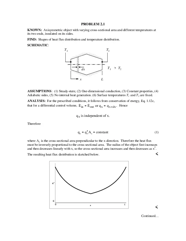
Document Preview (83 of 4073 Pages)

User generated content is uploaded by users for the purposes of learning and should be used following SchloarOn's honor code & terms of service.
You are viewing preview pages of the document. Purchase to get full access instantly.

Shop by Category See All


Shopping Cart (0)

Your bag is empty

Don't miss out on great deals! Start shopping or Sign in to view products added.

Shop What's New Sign in